
Moulage par injection Shrinkage: How to Control Part Dimensions from Conception de moules to Production
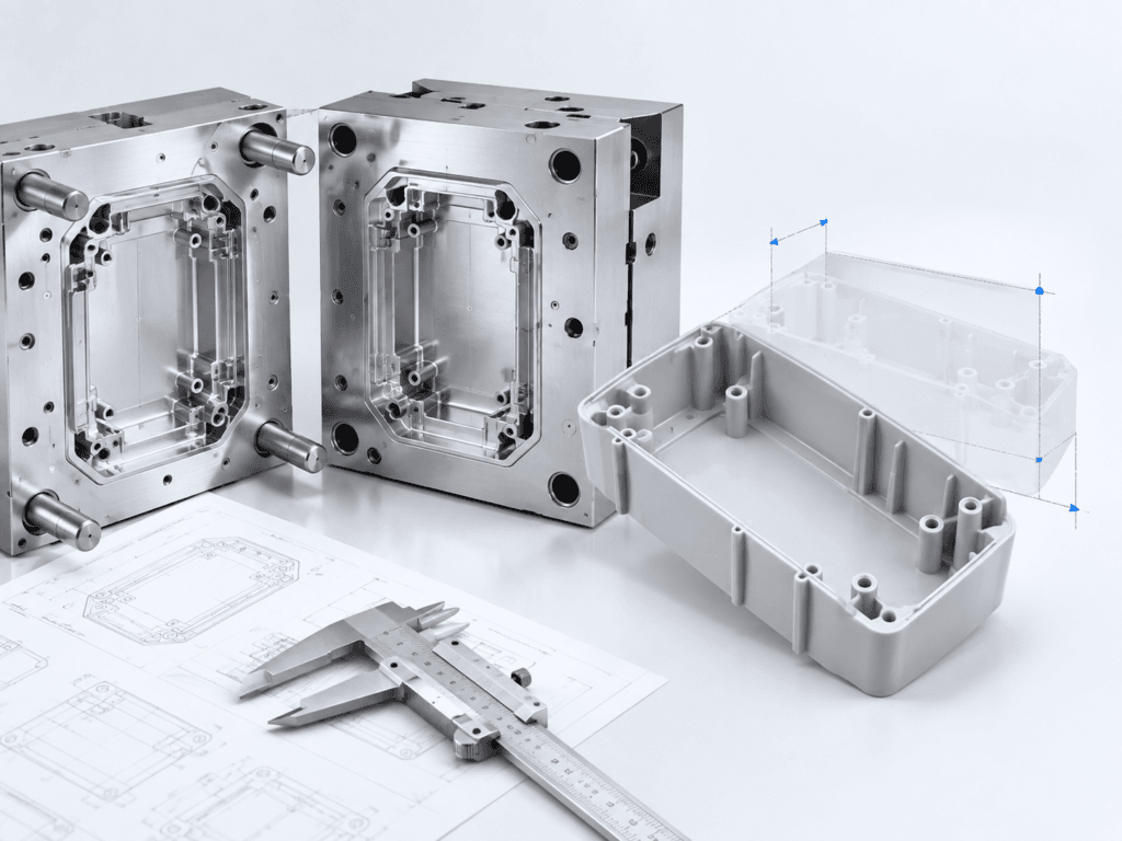
Injection molding shrinkage is one of the most important factors affecting the dimensional accuracy of plastic parts. A mold cavity is rarely manufactured to exactly the same dimensions as the final plastic component. Instead, mold designers enlarge cavity dimensions according to the expected material shrinkage.
However, shrinkage is not simply a fixed percentage taken from a material datasheet. It is influenced by polymer type, fiber reinforcement, wall thickness, gate position, flow direction, packing pressure, mold temperature, part geometry, and even the time at which the finished part is measured.
For mold manufacturers and product engineers, the real challenge is therefore not “What is the shrinkage rate?” but “How should shrinkage be predicted, distributed, validated, and corrected?”
This article focuses on the engineering application of shrinkage during mold development rather than repeating general material-selection or injection-molding design topics.
1. What Is Injection Molding Shrinkage?
Injection molding shrinkage is the dimensional reduction that occurs when molten plastic cools and solidifies after molding.
During injection, polymer enters the cavity at elevated temperature. As the material cools, its specific volume decreases. Additional dimensional changes can occur after ejection as the molded component continues cooling and reaches environmental equilibrium.
A simplified engineering calculation is:
Mold Dimension = Target Part Dimension × (1 + Shrinkage Rate)
For example, if a finished dimension must be 100.00 mm and the estimated shrinkage is 0.6%, the preliminary mold dimension would be approximately:
100 × 1.006 = 100.60 mm
In actual mold design, however, applying 0.6% uniformly to every dimension may produce an inaccurate part because shrinkage can vary by direction and geometry.
2. Typical Shrinkage Ranges of Injection Molding Materials
Different polymer families behave differently during cooling. Amorphous plastics generally exhibit lower and more predictable shrinkage, while semi-crystalline plastics frequently show higher shrinkage.
The following values should be treated as preliminary engineering ranges, not guaranteed values for a specific resin grade.
| Matériel | Typical Molding Shrinkage | General Behavior |
|---|---|---|
| ABS | 0.4–0.7% | Relatively stable |
| PC | 0.5–0.7% | Low, predictable shrinkage |
| PC/ABS | 0.4–0.7% | Good dimensional stability |
| PMMA | 0.2–0.8% | Generally low shrinkage |
| PP | 1.0–2.5% | Higher shrinkage |
| PEHD | 1.5–3.0% | High shrinkage |
| PA6 | 0.7–1.5% | Sensitive to processing and moisture |
| PA66 | 1.0–2.0% | Relatively high dimensional change |
| POM | 1.5–2.5% | High crystalline shrinkage |
| PA + Glass Fiber | 0.2–1.0% | Strongly directional |
For production tooling, the resin supplier’s grade-specific technical data should be checked before finalizing the cavity dimensions.
3. Shrinkage Is Not Always Uniform
One of the most important concepts in precision mold design is anisotropic shrinkage.
A molded component can shrink differently:
- Along the melt-flow direction
- Across the melt-flow direction
- Through its thickness
- Near the gate
- At the end of filling
- Around ribs, bosses, holes, and structural features
This becomes particularly important when processing glass-fiber- or carbon-fiber-reinforced polymers.
Fibers tend to orient according to melt flow. Because the reinforcement restricts polymer contraction, shrinkage parallel to fiber orientation can differ significantly from shrinkage perpendicular to it.
| Material Condition | Flow-Direction Shrinkage | Transverse Shrinkage |
|---|---|---|
| Unfilled polymer | Difference usually moderate | Difference usually moderate |
| Glass-filled polymer | Often significantly reduced | Usually higher |
| Carbon-fiber polymer | Very low possible | Directional difference can be substantial |
Therefore, simply scaling the complete CAD model by one shrinkage percentage may be insufficient for high-precision reinforced components.
4. Why Gate Position Can Change Final Dimensions
Gate design affects more than filling.
It also determines how efficiently packing pressure reaches different regions of the cavity.
Plastic near the gate normally remains connected to the pressurized melt longer. Areas far away from the gate may freeze earlier and receive less effective packing. Consequently, volumetric shrinkage can vary across a single component.
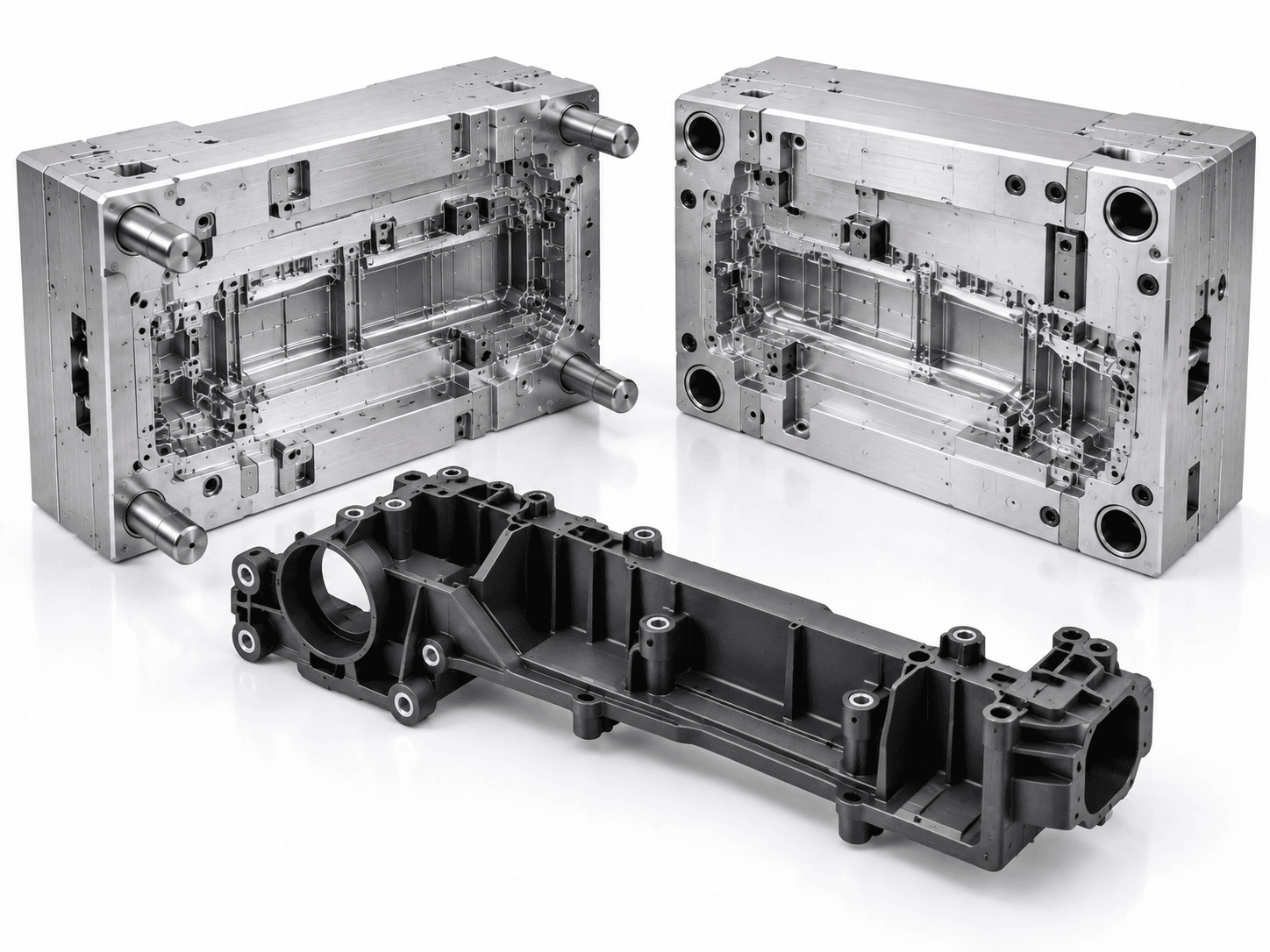
Consider a long rectangular housing.
If the gate is positioned at one end, the pressure history near the gate may be substantially different from the pressure history at the opposite end. This can contribute to dimensional variation, warpage, sink marks, and uneven shrinkage.
For dimensionally sensitive components, gate location should therefore be evaluated together with:
flow length + pressure distribution + fiber orientation + critical dimensions + expected shrinkage.
This is one reason Moldflow analysis can be valuable before mold steel is cut.
5. Processing Parameters Also Affect Shrinkage
Two molds manufactured to identical cavity dimensions do not necessarily produce parts with identical dimensions if their molding conditions are different.
Packing Pressure and Holding Time
Higher effective packing pressure generally introduces additional material into the cavity before gate freeze, helping compensate for volumetric contraction.
Insufficient packing can result in:
- Greater dimensional shrinkage
- Retassures
- Vides internes
- Part-weight variation
Température du moule
Mold temperature influences crystallization, cooling rate, residual stress, and dimensional behavior.
For semi-crystalline materials such as PP, PA and POM, changes in thermal history can noticeably affect final dimensions.
Température de fusion
Excessively high melt temperature increases the thermal difference between the injected polymer and the final cooled component. However, its actual dimensional effect must be considered together with packing, mold temperature and material characteristics.
Temps de refroidissement
A component ejected too early may continue contracting or deforming outside the mold.
This means apparent cycle-time improvements can sometimes create dimensional instability.
6. Wall Thickness Creates Local Shrinkage Differences
Part geometry also affects shrinkage.
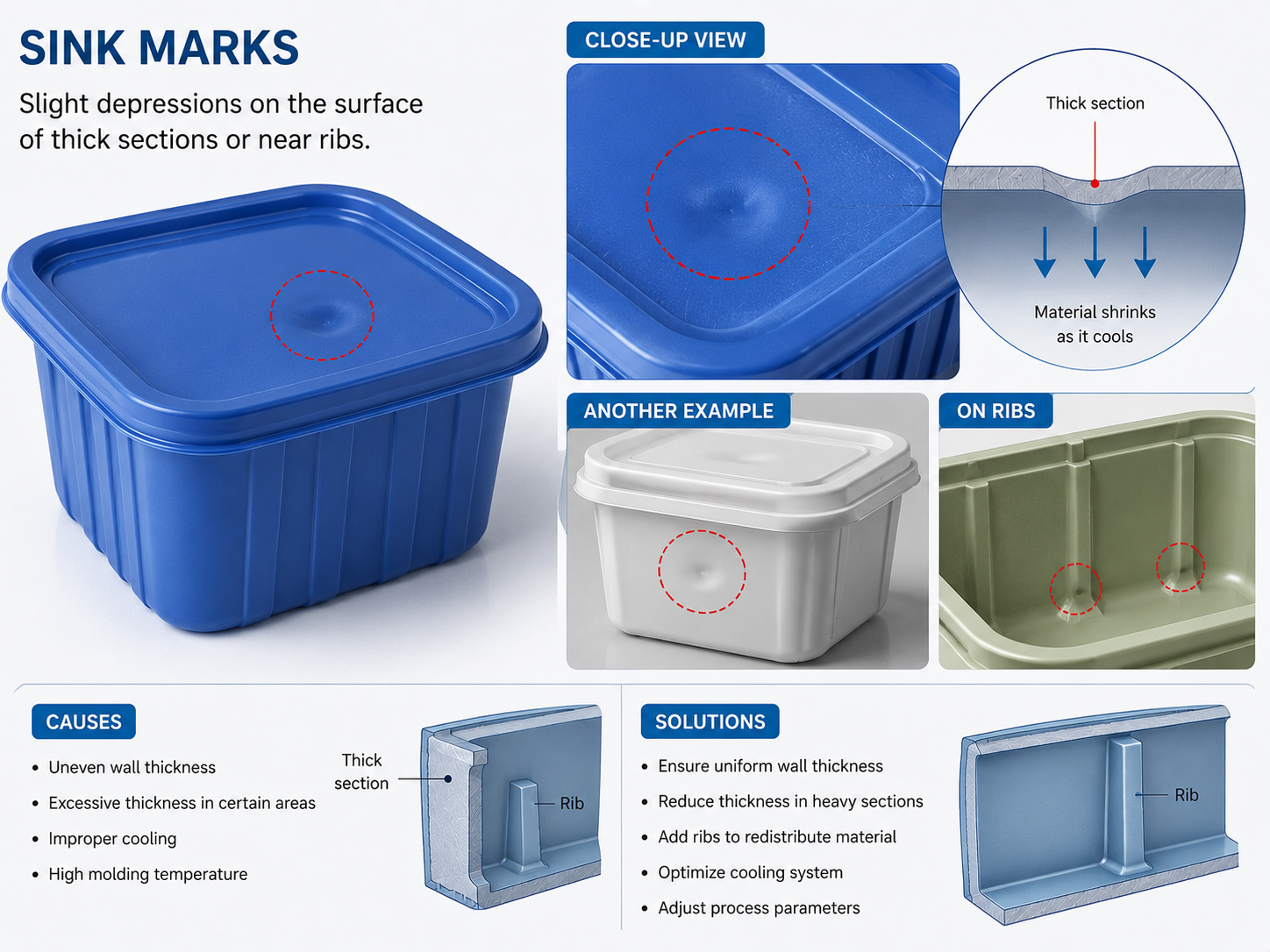
A thick region cools more slowly than a thin region. If a nominal 2.0 mm wall suddenly becomes 4.0 mm around a boss or structural junction, the thicker area experiences a different thermal history.
This can create:
- Local sink marks
- Differential shrinkage
- Internal stress
- Gauchissement
- Dimensional deviation
Ribs and bosses should therefore be designed to provide mechanical performance without creating unnecessarily large material accumulations.
7. Shrinkage and Warpage Are Related—but Not the Same
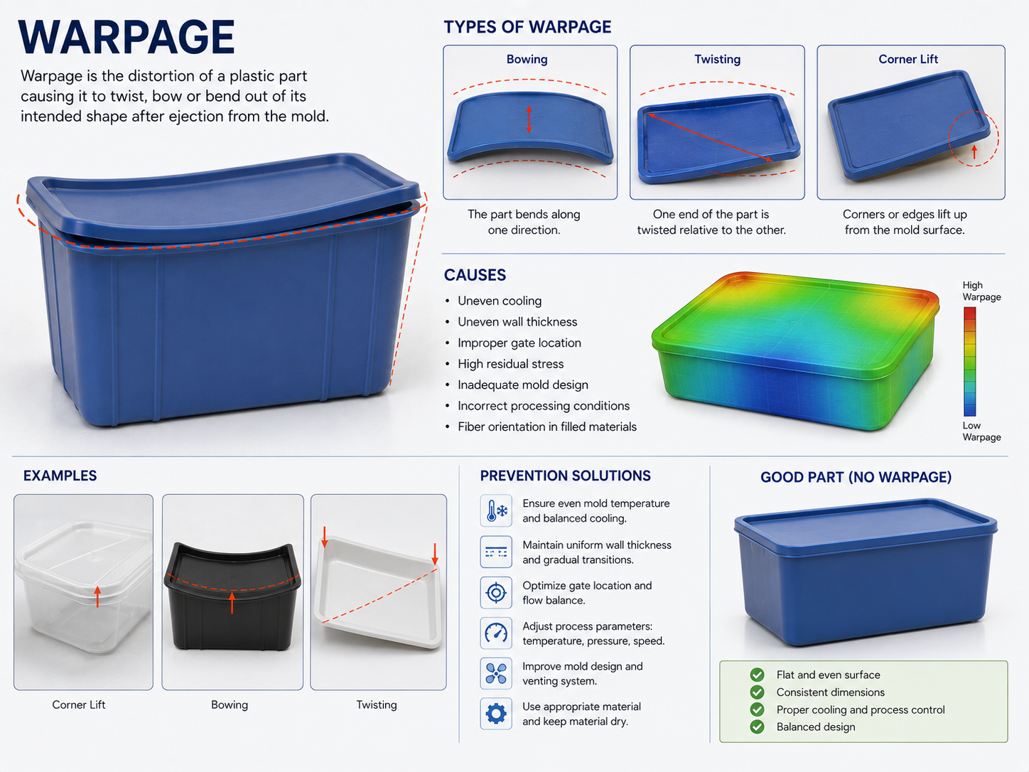
Shrinkage describes dimensional contraction. Warpage describes distortion caused by non-uniform shrinkage and internal stresses.
A molded plate, for example, might have an acceptable average shrinkage rate while still bending significantly.
Typical causes include:
| Cause | Possible Result |
|---|---|
| Uneven wall thickness | Local differential shrinkage |
| Uneven mold cooling | Part bending or twisting |
| Fiber orientation | Directional deformation |
| Poor gate position | Unbalanced packing |
| Early ejection | Post-ejection deformation |
| Different cavity temperatures | Dimensional inconsistency |
This distinction is critical during mold trials. Increasing the cavity dimension cannot necessarily solve a warpage problem.
The engineering team must first determine whether the dimensional error originates from global shrinkage, localized shrinkage, or deformation.
8. Critical Dimensions Should Be Managed Separately
For general plastic products, a single nominal shrinkage factor may be sufficient during preliminary mold design.
For precision components, critical dimensions should be identified during DFM.
Les exemples incluent :
- Bearing locations
- Interfaces de connecteurs
- Assembly holes
- Sealing surfaces
- Snap-fit positions
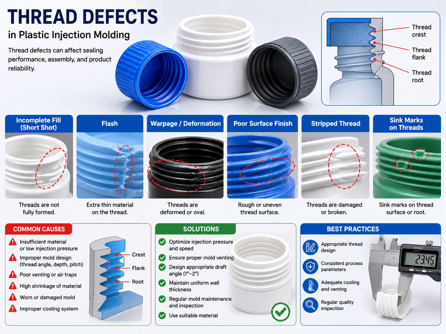
- Thread dimensions
- Gear center distances
- PCB mounting locations
Instead of asking whether the complete component is “within shrinkage,” engineers should evaluate whether each functional dimension remains within its tolerance after molding.
This approach is especially important when one component interfaces with metal inserts, electronic components or other precision assemblies.
9. Mold Trial Data Is More Valuable Than Theoretical Shrinkage Alone
The first mold trial provides actual dimensional information under defined molding parameters.
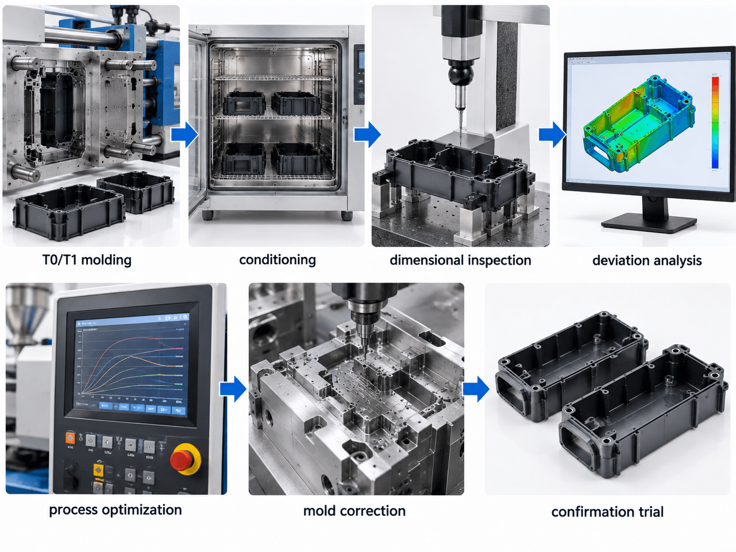
A practical validation process can follow:
T0/T1 molding → conditioning → dimensional inspection → deviation analysis → process optimization → mold correction → confirmation trial
Parts should not always be measured immediately after ejection. The measurement procedure should define the conditioning time, temperature, measurement equipment and datum system.
For high-precision projects, a CMM can provide considerably more useful information than checking only a few dimensions with calipers.
10. Correcting Shrinkage After the First Mold Trial
Experienced mold manufacturers normally consider potential dimensional correction when designing critical areas.
Suppose a specification requires:
150.00 ± 0.20 mm
The T1 sample measures:
149.45 mm
The engineering team should not immediately modify the steel.
First, verify:
- Is the molding process stable?
- Is the correct production material being used?
- Are packing pressure and holding time optimized?
- Has the part reached dimensional stability?
- Is the deviation consistent across multiple samples?
- Is the error caused by shrinkage or warpage?
Only after these variables are controlled should mold modification be considered.
Where possible, mold designers may intentionally leave steel-safe conditions around highly critical dimensions, making subsequent adjustment easier and less expensive.
11. A Better Shrinkage-Control Strategy
Successful shrinkage management starts before mold manufacturing and continues through production validation.
| Project Stage | Shrinkage Control Action |
|---|---|
| Conception de produits | Identify critical dimensions and tolerances |
| Sélection des matériaux | Confirm exact resin grade |
| DFM | Review geometry and dimensional risks |
| Moldflow | Evaluate flow, packing and warpage |
| Conception de moules | Apply appropriate shrinkage compensation |
| Fabrication de moules | Maintain steel-safe strategy where appropriate |
| T0/T1 Trial | Establish controlled processing conditions |
| Inspection | Measure critical dimensions systematically |
| Optimization | Adjust molding parameters first |
| Mold Modification | Correct confirmed dimensional deviations |
| Production | Lock the validated process window |
This approach transforms shrinkage from a simple percentage into a controlled engineering variable.
Conclusion
Injection molding shrinkage cannot be controlled effectively by copying a percentage from a material datasheet and scaling the complete CAD model.
Accurate dimensional control requires understanding the interaction between material behavior, fiber orientation, gate position, packing pressure, wall thickness, cooling conditions, mold design and post-molding dimensional stability.
For simple components, conventional shrinkage compensation may work well. For tight-tolerance housings, gears, connectors, mechanical components and fiber-reinforced parts, shrinkage should be treated as part of the complete DFM, simulation, mold-trial and dimensional-validation process.
The most reliable mold development strategy is therefore to predict shrinkage before tooling, measure it during trials, distinguish shrinkage from warpage, and correct the mold only after the molding process has been stabilized.
Obtenir le dernier prix ? Nous répondrons dès que possible (dans les 12 heures)
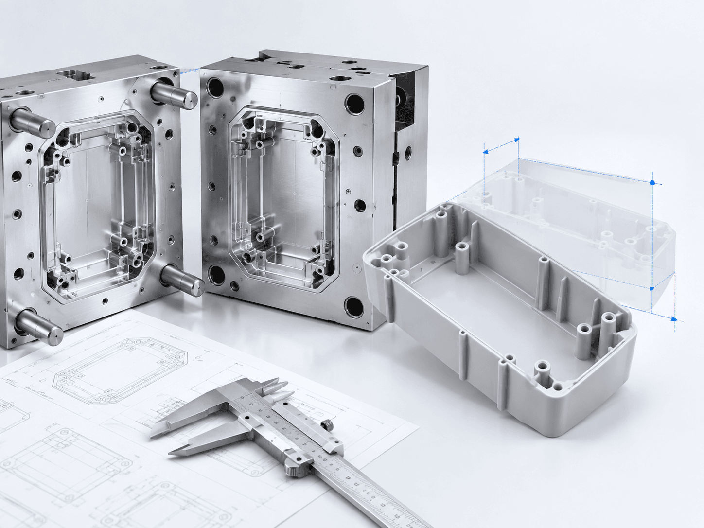
Injection Molding Shrinkage: How to Control Part Dimensions from Mold Design to Production
Learn how injection molding shrinkage affects mold dimensions, tolerances and warpage, and how material, gate design, packing, cooling and mold trials help control final plastic part dimensions.
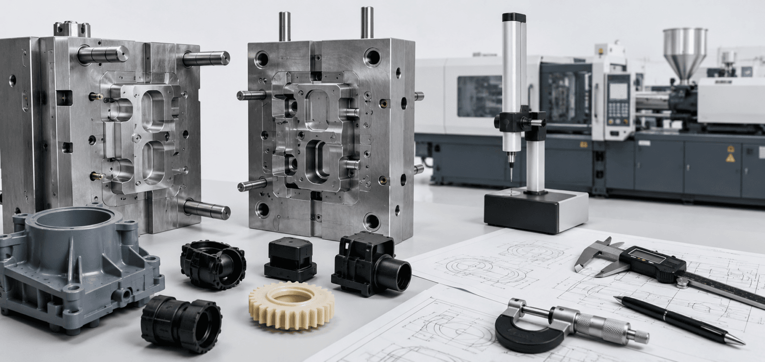
How to Choose the Right Injection Molding Supplier: A Practical Buyer’s Guide
Learn how to choose a reliable injection molding supplier by evaluating DFM capability, mold manufacturing, materials, quality control, production capacity, pricing, mold maintenance and technical communication.
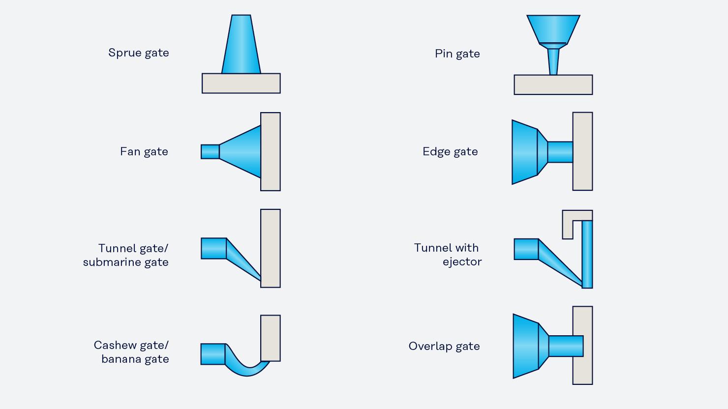
Types de seuils de moulage par injection plastique : sélection, principes de conception, avantages et applications
La conception du seuil est l'un des aspects les plus critiques de l'ingénierie des moules d'injection plastique. Bien que le seuil soit généralement le plus petit élément du système de canaux, il a une influence significative sur l'écoulement de la matière fondue, la pression de compactage, l'efficacité du refroidissement, l'aspect de la pièce, le temps de cycle et la qualité globale du produit.
Un seuil mal conçu peut provoquer de nombreux défauts de moulage, notamment des remplissages incomplets, des retassures, des lignes de soudure, des jets, des brûlures, un vestige de seuil excessif et un gauchissement des pièces. Inversement, le choix du type et de l'emplacement de seuil appropriés contribue à garantir un remplissage équilibré, une précision dimensionnelle constante et une production efficace.