
Thermal Expansion in Outdoor Injection Molded Parts: Design Guidelines for Temperature Cycling and Reliable Assembly

สารบัญ
บทนำ
Outdoor injection molded plastic components are exposed to continuous temperature fluctuations. A housing installed outdoors may experience intense solar heating during the day, rapid cooling at night, and significant seasonal temperature changes.
These conditions can create engineering problems that are not immediately visible during prototype assembly or initial mold trials.
Plastic components expand when heated and contract when cooled. When these dimensional changes are restricted by metal fasteners, aluminum frames, rigid connectors or neighboring components, internal stresses can develop.
Over time, these stresses may contribute to cracking, deformation, loose fasteners, assembly interference and reduced product reliability.
For outdoor equipment manufacturers, thermal expansion should therefore be considered during product design, DFM analysis, mold engineering and production validation.
This article explains how to manage temperature-related dimensional changes in outdoor injection molded components.
1. Why Outdoor Temperature Changes Matter
Outdoor products experience more complex thermal conditions than indoor components.
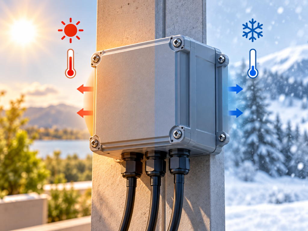
An enclosure may be exposed to ambient temperatures below freezing during winter and substantially higher surface temperatures under direct sunlight during summer.
Dark-colored plastic housings can absorb significant solar radiation, causing their surface temperature to rise above the surrounding air temperature.
These changes affect the dimensions and mechanical behavior of the plastic.
Potential problems include:
Expansion-related assembly interference
Cracking around rigid mounting points
Distortion of long plastic panels
Reduced snap-fit retention
Fastener loosening
Stress accumulation around metal inserts
The risk increases when a plastic component is connected to a material with a different coefficient of thermal expansion.
2. Understanding the Coefficient of Thermal Expansion
The coefficient of linear thermal expansion, commonly called CTE, describes how much a material changes in length for a given temperature change.
A simplified calculation is:
ΔL = L × α × ΔT
Where:
ΔL = Change in length
L = Original length
α = Coefficient of linear thermal expansion
ΔT = Temperature change
Consider a 250 mm plastic housing with a CTE of 70 × 10⁻⁶/K.
If the temperature changes by 80°C, the estimated free thermal expansion across that temperature range is:
250 × 70 × 10⁻⁶ × 80 = 1.40 mm
This movement may seem small, but it can become significant when the housing is rigidly attached to a metal structure.
Actual thermal expansion depends on the exact material grade, reinforcement, temperature range and part orientation.
Typical Thermal Expansion Comparison
| วัสดุ | Approximate Linear CTE (×10⁻⁶/K) | Design Consideration |
|---|---|---|
| เอบีเอส | 70–110 | Moderate to high expansion |
| พีซี | 60–75 | Relatively stable engineering plastic |
| พีพี | 100–180 | High expansion potential |
| Glass-fiber-reinforced plastics | Strongly grade- and direction-dependent | Fiber orientation matters |
| Aluminum | 22–24 | Expands less than most unfilled plastics |
| Carbon steel | 11–13 | Relatively low expansion |
These values are illustrative ranges. Final calculations should use the selected material grade’s technical data.
3. Plastic and Metal Components Expand Differently
Many outdoor products combine plastic housings with aluminum brackets, steel screws, threaded inserts or metal mounting frames.
Because these materials expand at different rates, their interfaces require careful engineering.
For example, a 250 mm plastic component with a CTE of 70 × 10⁻⁶/K may change approximately 1.40 mm over an 80°C temperature range.
An aluminum component of the same length, using a CTE of 23 × 10⁻⁶/K, would change approximately 0.46 mm.
The difference is approximately 0.94 mm.
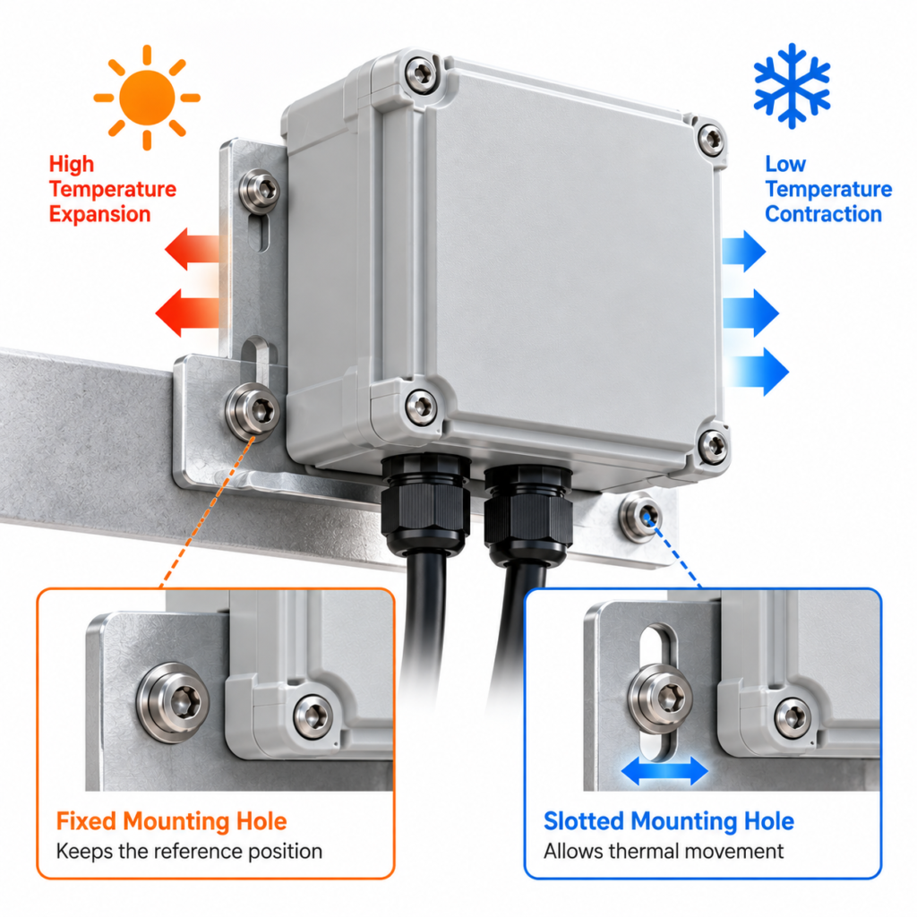
If the components are rigidly connected at both ends, this differential movement can generate stresses around mounting holes and fasteners.
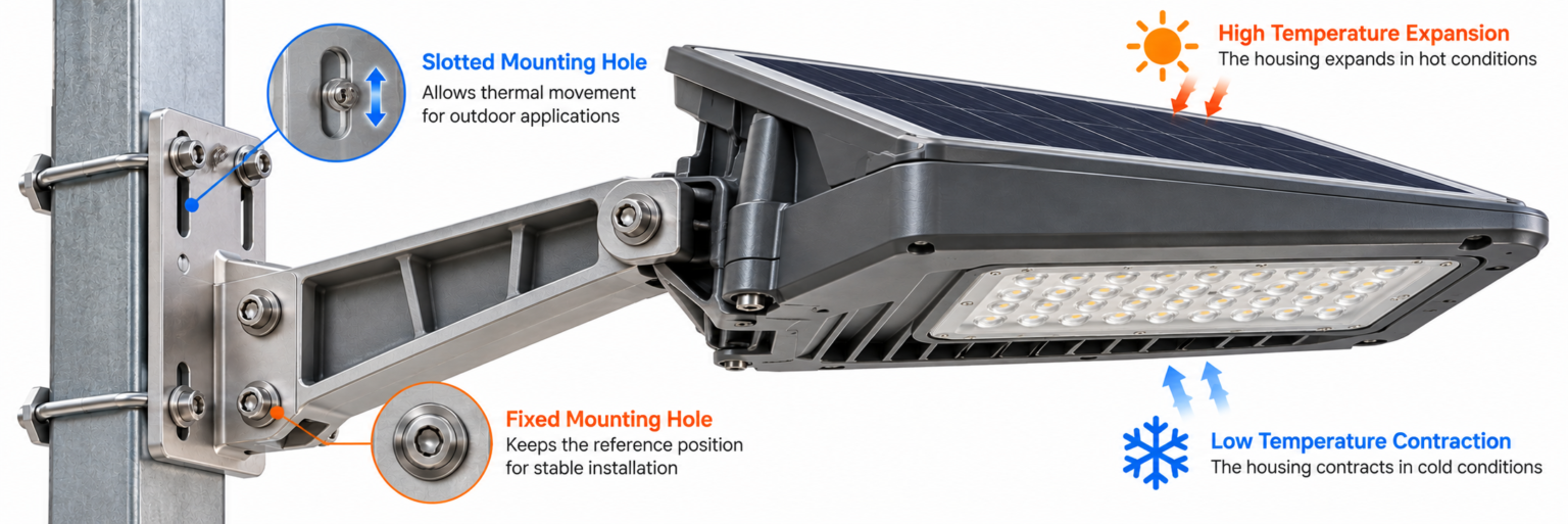
A better approach is often to establish one fixed mounting position while allowing controlled movement at another location.
4. Designing Mounting Holes for Thermal Movement
Mounting-hole geometry plays an important role in outdoor plastic assemblies.
A rigid mounting arrangement may work perfectly at room temperature but develop excessive stress after repeated heating and cooling.
For longer components, engineers may consider elongated mounting holes, floating supports or specially designed mounting brackets.
The objective is to accommodate predictable thermal movement without sacrificing structural stability.
However, elongated holes must be designed in the expected direction of expansion. Fasteners should also be arranged so that the slot can actually move when necessary.
The following table summarizes common problems and solutions.
| Design Problem | Potential Failure | โซลูชันทางวิศวกรรม |
|---|---|---|
| Two rigid mounting points | Thermal stress | Fixed and floating mounting strategy |
| Tight metal insert interface | Local cracking | Review expansion and surrounding wall thickness |
| Long plastic panel | Buckling or distortion | Allow expansion clearance |
| Excessive screw clamping | Restricted movement | Controlled fastening design |
| Rigid plastic-to-metal joint | การรวมตัวของความเค้น | Flexible interface or compliant support |
| Insufficient assembly gap | Component interference | Temperature-based clearance calculation |
Mounting features must also meet mechanical load requirements, including vibration, wind and installation forces.
5. Thermal Expansion and Snap-Fit Design
Snap-fit connections are widely used in outdoor electrical housings, lighting products, agricultural equipment and protective covers.
They reduce assembly time and may eliminate additional fasteners.
However, snap-fit performance can change with temperature.
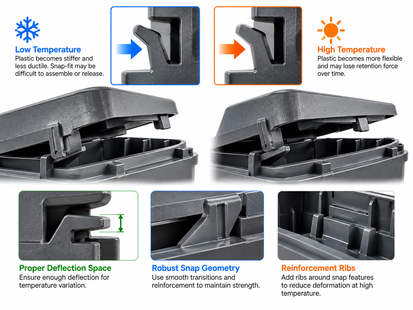
At elevated temperatures, some plastics become more flexible and may experience greater stress relaxation. At low temperatures, certain materials become less ductile and more sensitive to impact or excessive deflection.
A snap-fit that works well during room-temperature assembly may therefore become difficult to release in winter or lose retention force after prolonged high-temperature exposure.
Designers should evaluate snap-fit geometry, engagement depth, allowable deflection and material behavior over the complete operating temperature range.
For critical outdoor applications, mechanical testing should include both high- and low-temperature conditions.
6. Glass-Fiber Reinforcement Changes Thermal Behavior
Glass-fiber-reinforced plastics are frequently selected for structural outdoor components because reinforcement can improve stiffness and reduce thermal expansion in certain directions.
However, fiber-reinforced plastics do not necessarily expand uniformly.
During injection molding, glass fibers orient according to the local melt-flow pattern.
As a result, thermal expansion parallel to the dominant fiber direction may differ substantially from expansion perpendicular to it.
This directional behavior can influence dimensional stability, particularly in long, thin or asymmetrical components.
For precision outdoor parts, designers should evaluate fiber orientation, gate position and the geometry of critical mounting features.
A single average CTE value may be insufficient for complex reinforced components.
7. Long-Term Heat Exposure and Plastic Creep
Thermal expansion is not the only concern at elevated temperatures.
Plastic components subjected to continuous mechanical loads can experience creep, a gradual deformation under sustained stress.
For example, a plastic screw boss compressed by a metal fastener may slowly deform during prolonged high-temperature exposure.
This can reduce clamping force or change the position of assembled components.
The risk depends on material properties, temperature, applied stress and exposure duration.
Possible engineering improvements include increasing local structural support, reducing unnecessary stress concentration, selecting suitable inserts and designing fastening systems that maintain reliable clamping performance.
Heat deflection temperature alone should not be treated as a complete indicator of long-term structural durability.
8. Mold Design and Dimensional Stability
Thermal performance is influenced not only by the product geometry but also by injection molding conditions.
Uneven wall thickness, cooling differences, gate position and fiber orientation can contribute to residual stress or warpage.
These effects may become more noticeable when molded parts experience temperature cycling.
For example, a large outdoor housing may appear flat after molding but deform when heated because of residual stresses or differences in thermal expansion.
The mold development team should therefore pay attention to:
Balanced filling and packing
Consistent cooling
ความหนาของผนังเท่ากัน
Critical mounting dimensions
Fiber orientation in reinforced materials
Dimensional stability after conditioning
Moldflow simulation may help identify potential deformation risks before tooling, although physical validation remains necessary.
9. Temperature Cycling and Product Validation
Outdoor plastic components should be evaluated under conditions representative of their intended operating environment.
Temperature cycling tests expose assemblies to repeated high- and low-temperature conditions to assess their dimensional and functional stability.
The test plan should consider the complete assembly, including plastic components, metal fasteners, inserts, snap-fits and any other critical interfaces.
Recommended Validation Plan
| Test | Main Purpose |
|---|---|
| High-temperature exposure | Evaluate heat-related deformation |
| Low-temperature exposure | Check cold-condition functionality |
| การทดสอบการเปลี่ยนแปลงอุณหภูมิสลับไปมา | Evaluate repeated expansion and contraction |
| การตรวจสอบมิติ | Measure dimensional changes |
| Snap-fit retention test | Verify locking performance |
| Fastener torque or retention check | Assess joint stability |
| Assembly inspection | Identify interference and cracking |
| Long-term creep evaluation | Assess deformation under sustained load |
Standards such as IEC 60068-2-14 can provide a framework for temperature-change testing when applicable.
The test temperature, dwell time, number of cycles and acceptance criteria should be established according to the actual product requirements.
10. Practical Example: Outdoor Sensor Housing
Consider an outdoor sensor enclosure mounted on an aluminum support.
The enclosure contains electronic components and uses several screws to attach to the metal bracket.
If all mounting holes are tightly constrained, repeated temperature changes may create stress around the screw bosses.
A more robust design may incorporate one fixed reference point, controlled expansion clearance and appropriately positioned floating mounting features.
The engineering team should also verify that the mounting strategy does not compromise electrical connector alignment or mechanical stability.
Before mass production, the complete assembly should undergo dimensional inspection and temperature cycling tests.
This approach helps identify thermal-related failures before they appear in field applications.
บทสรุป
Thermal expansion is an important but sometimes overlooked factor in outdoor injection molded plastic product design.
Temperature changes can influence dimensions, mounting interfaces, snap-fit performance, fastener stability and long-term structural reliability.
The challenge becomes particularly significant when plastic components are assembled with aluminum, steel or other materials that expand at different rates.
Successful outdoor product development requires engineers to consider thermal movement during CAD design, evaluate critical features during DFM, control dimensional stability during molding and validate the complete assembly through representative temperature testing.
By designing for thermal movement rather than attempting to eliminate it, manufacturers can reduce cracking, deformation, assembly failures and costly tooling modifications.
รับราคาล่าสุด? เราจะตอบกลับโดยเร็วที่สุด (ภายใน 12 ชั่วโมง)

Thermal Expansion in Outdoor Injection Molded Parts: Design Guidelines for Temperature Cycling and Reliable Assembly
Learn how thermal expansion, temperature cycling, plastic creep and metal-to-plastic assemblies affect outdoor injection molded parts, with practical design solutions.
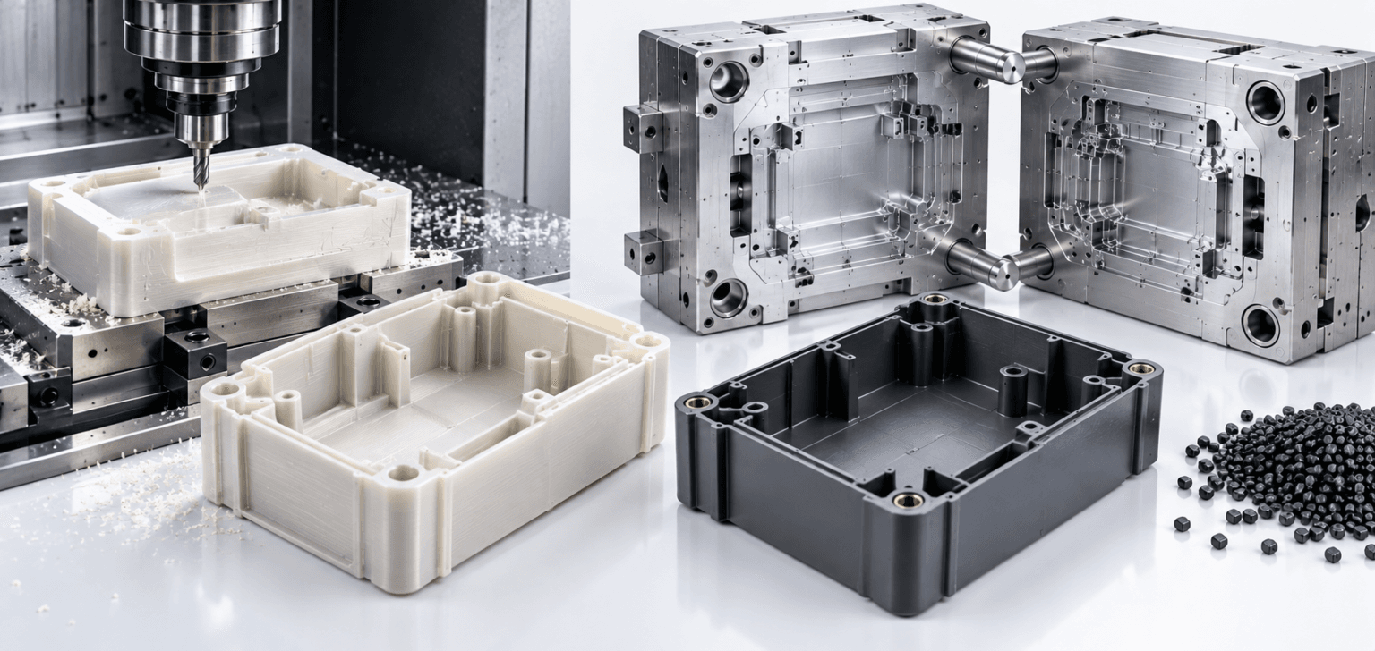
CNC Plastic Prototypes vs. Injection Molded Parts: Key Differences Engineers Should Understand
Compare CNC plastic prototypes and injection molded parts in material properties, dimensions, warpage, surface finish, geometry, cost and production performance.
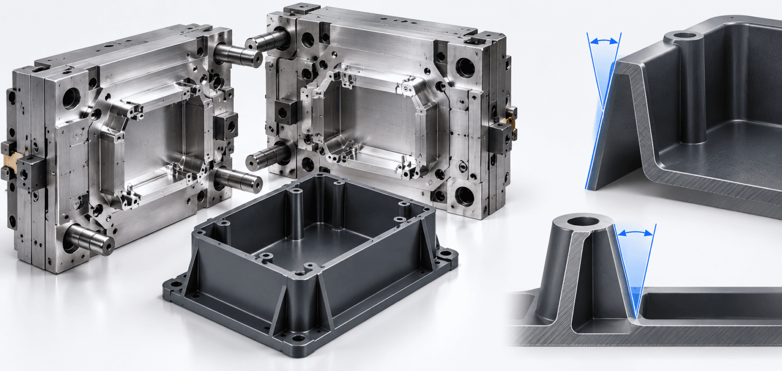
Draft Angle in Injection Mold Design: Improving Part Quality, Ejection and Tooling Efficiency
Discover how draft angles affect injection mold design, part ejection, surface texture, dimensional accuracy, ribs, bosses and long-term tooling performance.