
สารบัญ
บทนำ
การฉีดขึ้นรูปพลาสติก is one of the most efficient manufacturing processes for producing high-quality plastic components with exceptional precision and repeatability. However, the quality of every molded product depends largely on the design and construction of the injection mold itself. A well-engineered mold is far more than a block of steel—it is a sophisticated mechanical system that controls molten plastic flow, cooling, part ejection, dimensional accuracy, and production efficiency.
An แม่พิมพ์ฉีดพลาสติก typically consists of dozens or even hundreds of precision-machined components working together throughout every molding cycle. Each component has a specific purpose, from guiding molten plastic into the cavity to removing the finished part without damage. Even minor improvements in mold structure can significantly reduce cycle time, improve product quality, extend mold life, and lower manufacturing costs.
For engineers, product designers, and purchasing professionals, understanding mold structure is essential when developing new products. Knowledge of mold components also helps simplify communication with mold manufacturers during product development and Design for Manufacturability (DFM) reviews.
At Samgo, injection mold manufacturing is our core expertise. Every mold is designed using advanced CAD software, DFM analysis, Moldflow simulation, and precision machining to ensure reliable long-term production. In this guide, we explain the essential components of an injection mold, how each system functions, and why proper mold design is critical for successful plastic injection molding.
What Is an Injection Mold Structure?
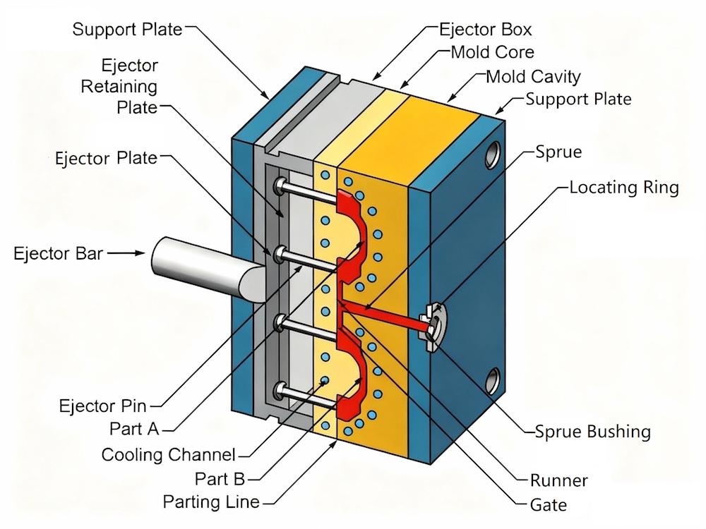
An แม่พิมพ์ฉีดพลาสติก structure refers to the complete mechanical system used to shape molten plastic into finished products. It consists of multiple integrated systems that control plastic flow, cooling, alignment, ejection, and movement during the molding cycle.
Unlike a simple metal tool, an injection mold is a precision assembly where every component must work together with high accuracy. The overall structure influences:
- Part quality
- ความแม่นยำด้านมิติ
- Surface finish
- Production speed
- Mold durability
- Maintenance requirements
- Manufacturing cost
A properly designed mold structure minimizes production defects such as flash, sink marks, warpage, short shots, and excessive wear while maximizing production efficiency.
Main Functions of an Injection Mold
| ฟังก์ชัน | Description |
|---|---|
| Plastic Forming | Shapes molten plastic into the desired geometry |
| การทำความเย็น | Removes heat quickly and evenly to shorten cycle time |
| Guiding | Ensures accurate alignment between mold halves |
| Ejection | Releases finished parts without damage |
| ระบายอารมณ์ | Allows trapped air to escape during filling |
| Support | Maintains structural rigidity under injection pressure |
Basic Components of an Injection Mold
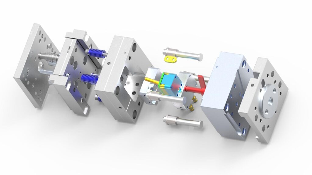
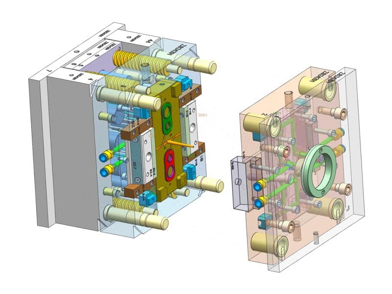
Although mold structures vary depending on the product, most injection molds include several fundamental systems.
Standard Mold Components
| ส่วนประกอบ | Primary Function |
|---|---|
| ฐานแม่พิมพ์ | Supports the complete mold assembly |
| Core | Forms the internal geometry of the plastic part |
| Cavity | Forms the external surface of the part |
| Sprue Bush | Transfers molten plastic into the runner system |
| Runner | Distributes molten plastic inside the mold |
| Gate | Controls material entry into the cavity |
| ช่องหล่อเย็น | Regulate mold temperature |
| Ejector System | Removes the molded part |
| Guide Pillars & Bushings | Ensure precise alignment |
| Return Pins | Reset the ejector system |
| Support Plates | Increase mold rigidity |
| Wear Plates | Reduce friction on moving components |
Each component must be manufactured with tight tolerances to ensure stable production over thousands—or even millions—of molding cycles.
Mold Base: The Foundation of the Mold
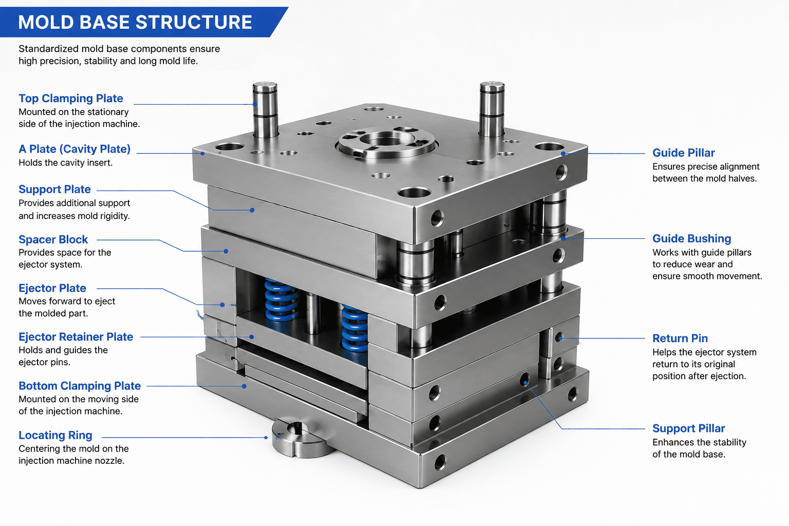
The mold base provides structural support for all other mold components. It keeps the mold rigid during injection, maintains alignment, and houses moving systems such as ejector plates and guide pillars.
Most professional mold makers use standardized mold base systems from manufacturers such as HASCO, DME, LKM, or FUTABA. Standardization simplifies maintenance, reduces lead times, and ensures compatibility with replacement components.
Typical Mold Base Components
| ส่วนประกอบ | วัตถุประสงค์ |
|---|---|
| Top Clamping Plate | Mounts the mold to the injection machine |
| A Plate | Holds the cavity insert |
| B Plate | Holds the core insert |
| Support Plate | Reinforces the mold structure |
| Spacer Blocks | Create space for the ejector system |
| Bottom Clamping Plate | Secures the moving half of the mold |
The selection of mold base size depends on part dimensions, projected area, injection pressure, and machine specifications.
Core and Cavity: Creating the Product Shape
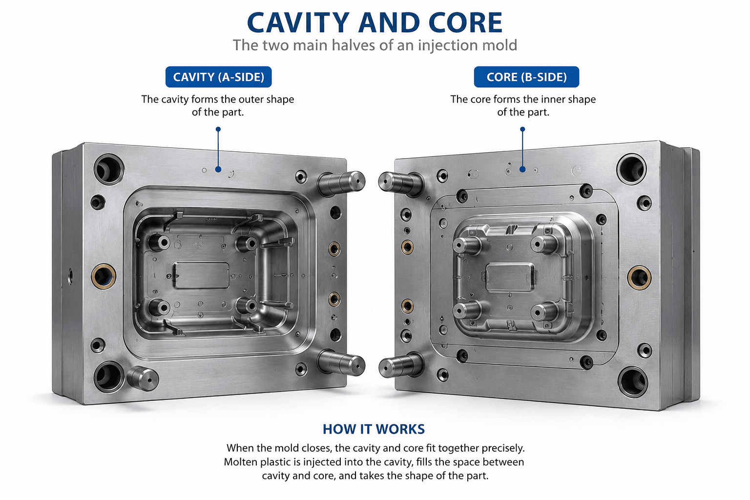
The core and cavity are the heart of every injection mold. Together, they define the final geometry of the molded part.
- The cavity forms the outer surface of the product.
- The core forms the internal features, such as holes, ribs, bosses, and mounting structures.
The gap between the core and cavity determines the wall thickness of the finished plastic part. High machining accuracy and excellent surface finishing are essential to ensure dimensional consistency and product appearance.
Common Mold Steels
| Steel Grade | Characteristics | การใช้งานทั่วไป |
|---|---|---|
| P20 | Good machinability, economical | General-purpose molds |
| 718H | Pre-hardened, excellent polishability | สินค้าอุปโภคบริโภค |
| NAK80 | Superior mirror finish | Cosmetic and transparent parts |
| S136 | Corrosion-resistant stainless steel | Medical, optical, and food-grade molds |
| H13 | ทนความร้อนสูง | High-temperature engineering plastics |
| 8407 | Long service life and wear resistance | High-volume production |
Choosing the correct mold steel depends on resin type, annual production volume, required surface finish, and expected mold life.
Runner System: Delivering Molten Plastic Efficiently
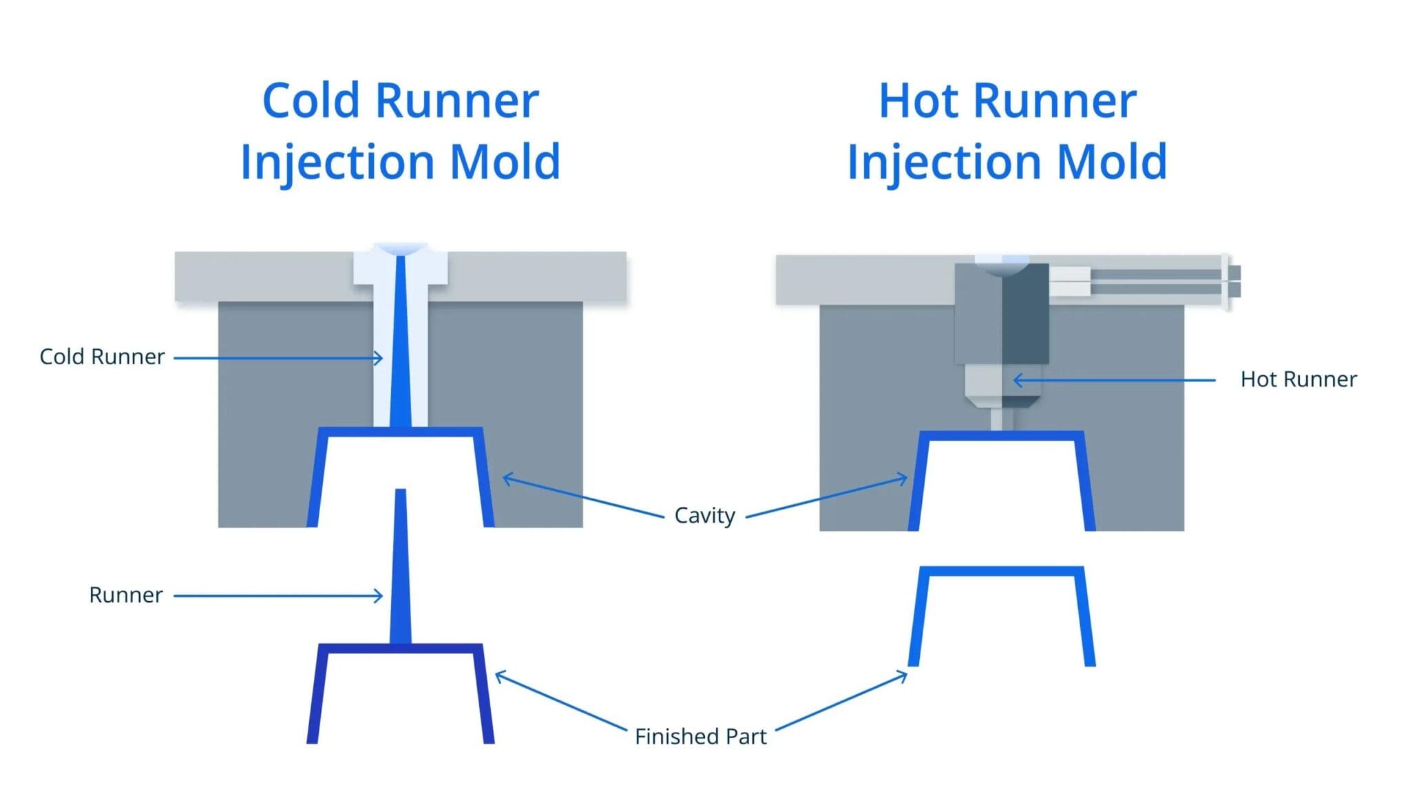
The runner system transports molten plastic from the injection machine nozzle to the mold cavity. A well-designed runner system ensures balanced filling, minimizes pressure loss, and reduces material waste. Poor runner design can lead to short shots, weld lines, excessive pressure, and inconsistent part quality.
There are two primary runner systems used in injection molds:
| Runner Type | Advantages | Limitations | การใช้งานทั่วไป |
|---|---|---|---|
| Cold Runner | Lower mold cost, simple maintenance | Produces runner waste | General consumer products |
| Hot Runner | No runner scrap, shorter cycle time | Higher tooling investment | High-volume production, cosmetic parts |
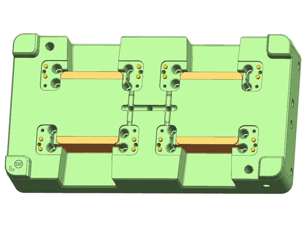
For multi-cavity molds, balanced runner layouts are essential to ensure that every cavity fills simultaneously, producing parts with consistent dimensions and appearance.
Gate System
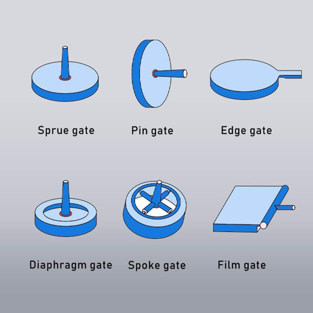
The gate is the final opening through which molten plastic enters the cavity. Its location, size, and type directly affect filling behavior, packing pressure, gate vestige, and cosmetic quality.
Common Gate Types
| Gate Type | Best For | Advantages |
|---|---|---|
| Edge Gate | General products | Easy machining and maintenance |
| Pin Gate | Multi-cavity molds | Small gate mark |
| Submarine Gate | Automatic degating | ประสิทธิภาพการผลิตสูง |
| Fan Gate | Thin-wall parts | Uniform material flow |
| Valve Gate | Premium appearance parts | No visible gate mark |
Gate selection should always consider product geometry, resin flow characteristics, wall thickness, and cosmetic requirements.
ระบบหล่อเย็น
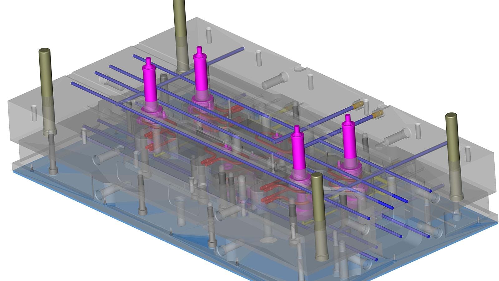
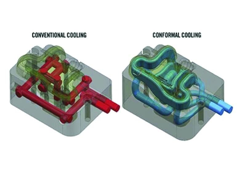
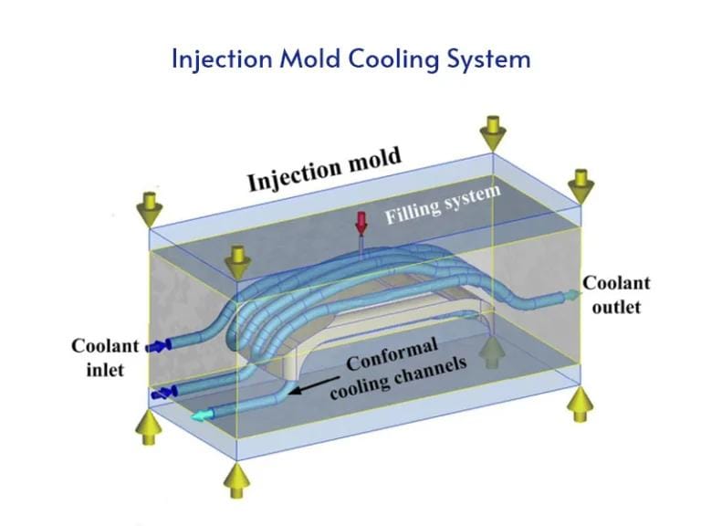
Cooling accounts for approximately 50–70% of the total injection molding cycle time, making it one of the most important systems within the mold.
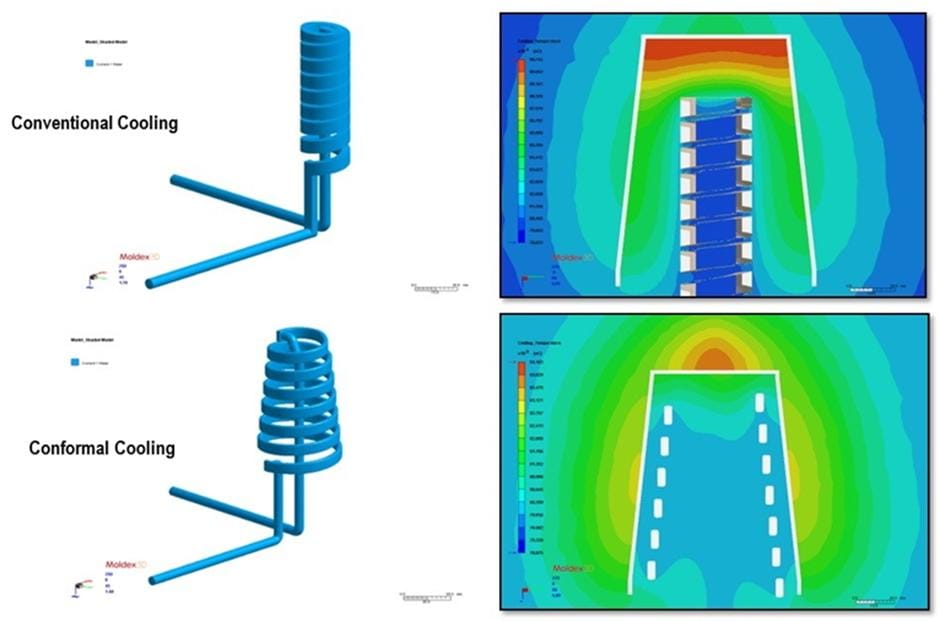
A properly designed cooling system removes heat uniformly, reducing cycle time while minimizing warpage and dimensional variation.
Common Cooling Components
- Straight cooling channels
- Baffles
- Bubblers
- Spiral cooling inserts
- Conformal cooling (3D printed inserts)
| Cooling Method | แอปพลิเคชันทั่วไป | ประโยชน์ |
|---|---|---|
| Straight Channels | Standard molds | Low cost |
| Baffle Cooling | Deep cores | Improved heat removal |
| Bubbler Cooling | Narrow core areas | Better temperature control |
| Conformal Cooling | Complex molds | Maximum cooling efficiency |
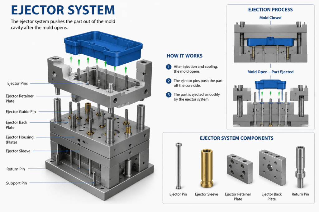
Ejection System
After cooling, the molded part must be removed without damaging its surface or geometry. The ejection system performs this task by applying controlled force to the molded component.
Common Ejection Methods
| Ejection Method | Typical Products |
|---|---|
| Ejector Pins | Most plastic components |
| Sleeve Ejectors | Cylindrical parts |
| Stripper Plate | Thin-wall containers |
| Air Ejection | Transparent products |
| Hydraulic Ejection | Large industrial parts |
Proper ejector placement helps prevent deformation, whitening, and surface marks.
Slider and Lifter Mechanisms
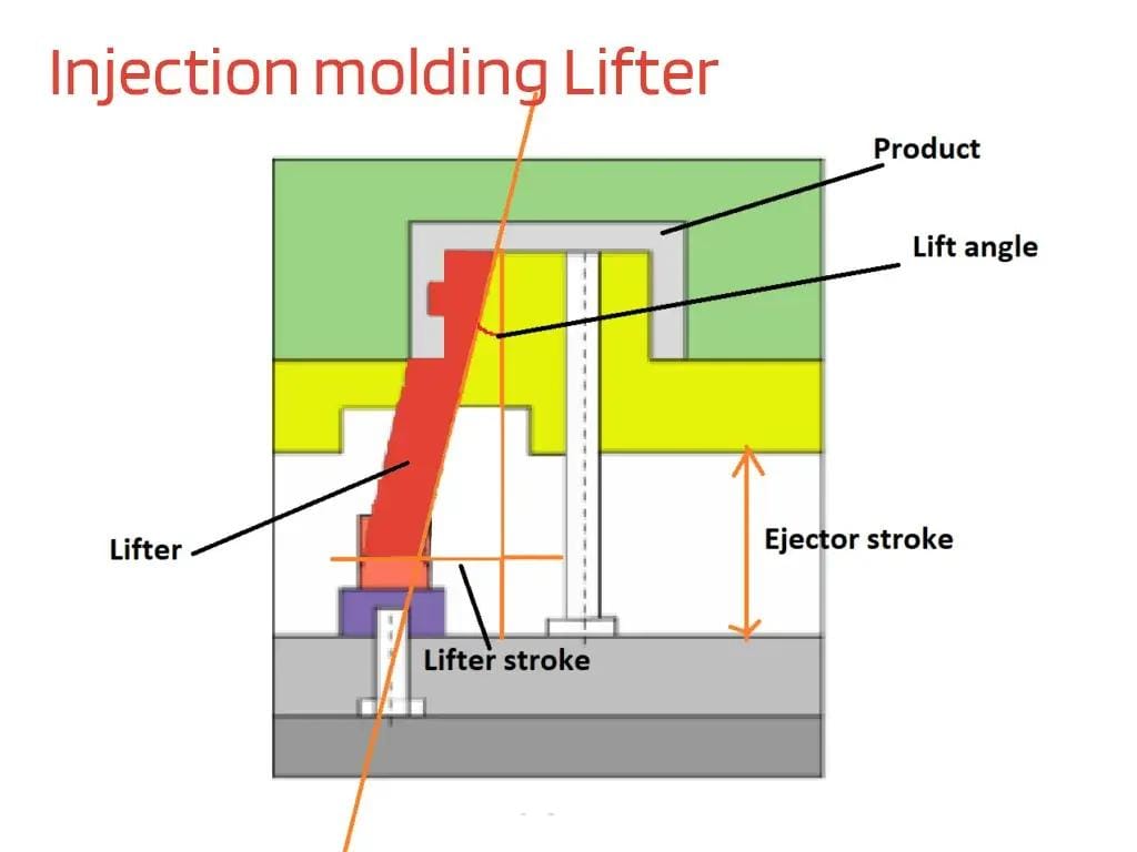
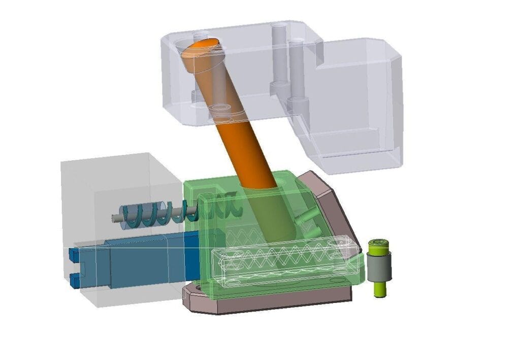
Many plastic parts include undercuts that cannot be released using a simple two-plate mold. Additional mechanisms such as sliders and lifters are required.
Sliders
Sliders move horizontally during mold opening to release external undercuts.
การใช้งานทั่วไปประกอบด้วย:
- Side holes
- Snap hooks
- Cable exits
- Connector features
Lifters
Lifters move upward and outward simultaneously to release internal undercuts.
การใช้งานทั่วไปประกอบด้วย:
- Internal locking tabs
- Hidden clips
- Complex internal geometries
These mechanisms increase mold complexity but allow highly functional part designs.
Venting System
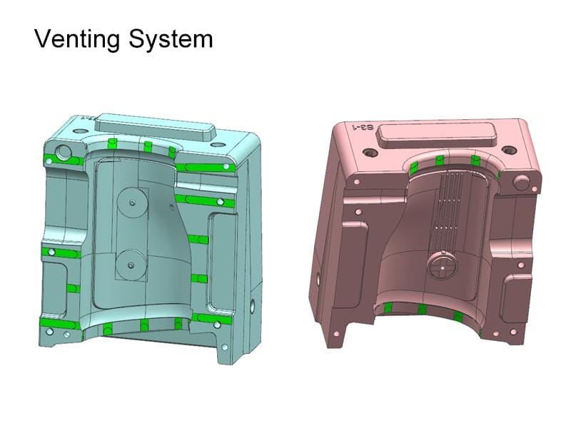
During injection, trapped air must escape from the cavity. Without adequate venting, compressed gases can create defects such as:
- รอยไหม้
- ช็อตสั้น
- Gas traps
- Poor surface finish
- การบรรจุไม่สมบูรณ์
Vent grooves are typically machined into the parting line or ejector pin locations and are carefully sized to allow gas to escape while preventing molten plastic from flashing.
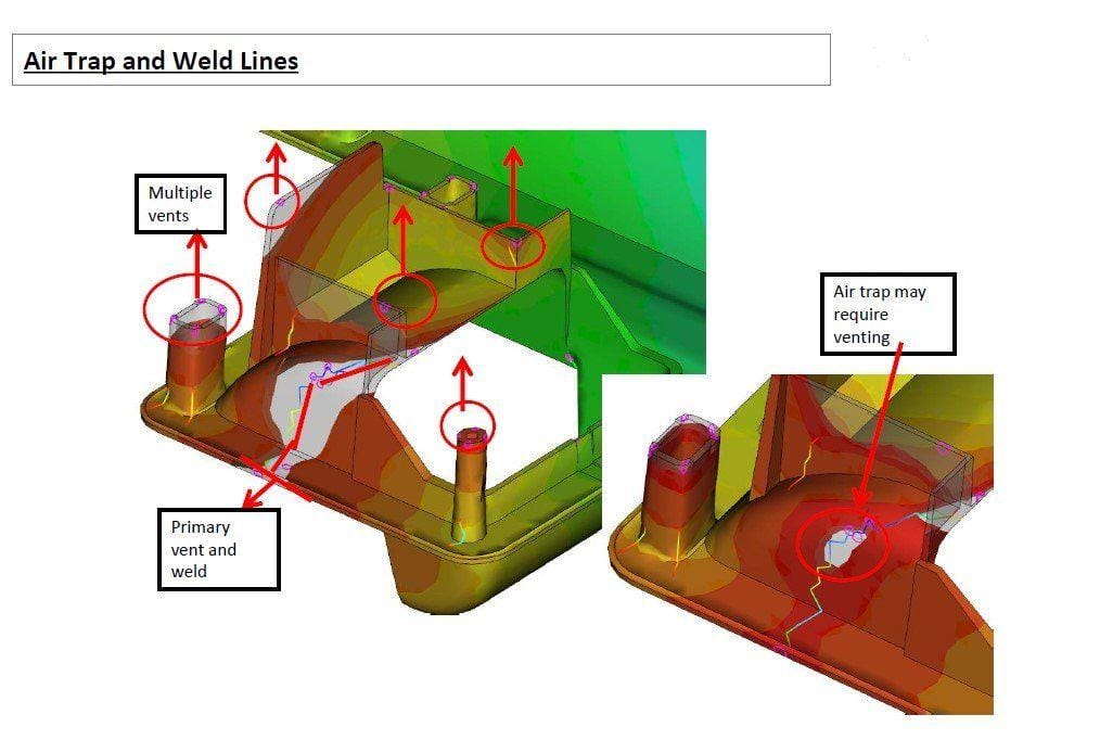
Injection Mold Manufacturing Process
Building a high-quality mold requires precision engineering and multiple machining processes.
Typical Manufacturing Workflow
| Step | Description |
|---|---|
| Product Review | Analyze customer drawings and requirements |
| การวิเคราะห์เพื่อการผลิต (DFM) | Optimize product for manufacturability |
| การจำลองโมลด์โฟลว์ | Predict filling, cooling, and warpage |
| การออกแบบแม่พิมพ์ | Develop complete 3D mold assembly |
| CNC Machining | Produce core, cavity, and mold plates |
| EDM & Wire EDM | Machine complex features |
| Polishing & Texturing | Achieve required surface finish |
| Mold Assembly | Assemble all mold components |
| T1 Mold Trial | Produce initial samples |
| Inspection & Optimization | Verify dimensions and performance |
| Final Approval | Prepare mold for mass production |
ทำไมต้องเลือก Samgo
At Samgo, we provide complete mold engineering solutions from concept to mass production.
Our Core Services
| บริการ | ประโยชน์ที่ลูกค้าได้รับ |
|---|---|
| การออกแบบผลิตภัณฑ์ | Optimized manufacturability |
| การวิเคราะห์เพื่อการผลิต (DFM) | ลดความเสี่ยงด้านเครื่องมือ |
| การจำลองโมลด์โฟลว์ | Improved mold performance |
| การผลิตแม่พิมพ์ความละเอียดสูง | อายุการใช้งานแม่พิมพ์ยาวนาน |
| การฉีดขึ้นรูปพลาสติก | การผลิตจำนวนมากอย่างเสถียร |
| การตรวจสอบคุณภาพ | คุณภาพสินค้าสม่ำเสมอ |
Our engineering team focuses on designing molds that maximize productivity, minimize maintenance, and deliver reliable performance throughout the mold’s service life.
Frequently Asked Questions (FAQ)
What is the most important component of an injection mold?
The core and cavity are the most critical components because they define the final shape, dimensions, and surface quality of the molded part.
What is the difference between a hot runner and a cold runner?
A hot runner keeps the plastic molten inside the mold, eliminating runner waste, while a cold runner solidifies after each cycle and must be removed or recycled.
Why is cooling system design so important?
An efficient cooling system shortens cycle time, improves dimensional stability, and reduces warpage, making it one of the biggest factors affecting production efficiency.
When are sliders and lifters required?
They are used when molded parts contain undercuts or side features that cannot be released by opening the mold in a straight direction.