
Inhaltsverzeichnis
Einführung
Kunststoffspritzgießen ist einer der effizientesten Fertigungsprozesse zur Herstellung hochwertiger Kunststoffkomponenten mit außergewöhnlicher Präzision und Wiederholgenauigkeit. Die Qualität jedes Spritzgussteils hängt jedoch stark vom Design und der Konstruktion des Spritzgießwerkzeugs selbst ab. Ein gut konstruiertes Werkzeug ist weit mehr als nur ein Stahlblock – es ist ein ausgeklügeltes mechanisches System, das den Fluss der Kunststoffschmelze, die Kühlung, die Teilauswerfung, die Maßhaltigkeit und die Produktionseffizienz steuert.
An Spritzguss besteht typischerweise aus Dutzenden oder sogar Hunderten von präzisionsgefertigten Komponenten, die während jedes Spritzgießzyklus zusammenarbeiten. Jede Komponente hat einen spezifischen Zweck, von der Führung des geschmolzenen Kunststoffs in den Hohlraum bis hin zur Entnahme des fertigen Teils ohne Beschädigung. Selbst geringfügige Verbesserungen der Formstruktur können die Zykluszeit erheblich verkürzen, die Produktqualität verbessern, die Lebensdauer der Form verlängern und die Herstellungskosten senken.
Für Ingenieure, Produktdesigner und Einkäufer ist das Verständnis der Werkzeugstruktur bei der Entwicklung neuer Produkte unerlässlich. Die Kenntnis der Werkzeugkomponenten trägt zudem dazu bei, die Kommunikation mit den Werkzeugherstellern während der Produktentwicklung und bei DFM-Prüfungen (Design for Manufacturability) zu vereinfachen.
Bei Samgo ist der Spritzgussformenbau unsere Kernkompetenz. Jede Form wird mithilfe fortschrittlicher CAD-Software, DFM-Analyse, Moldflow-Simulation und Präzisionsbearbeitung entwickelt, um eine zuverlässige langfristige Produktion zu gewährleisten. In diesem Leitfaden erklären wir die wesentlichen Komponenten einer Spritzgussform, wie die einzelnen Systeme funktionieren und warum ein ordnungsgemäßes Formendesign für einen erfolgreichen Kunststoffspritzguss von entscheidender Bedeutung ist.
Was ist eine Spritzgusswerkzeugstruktur?
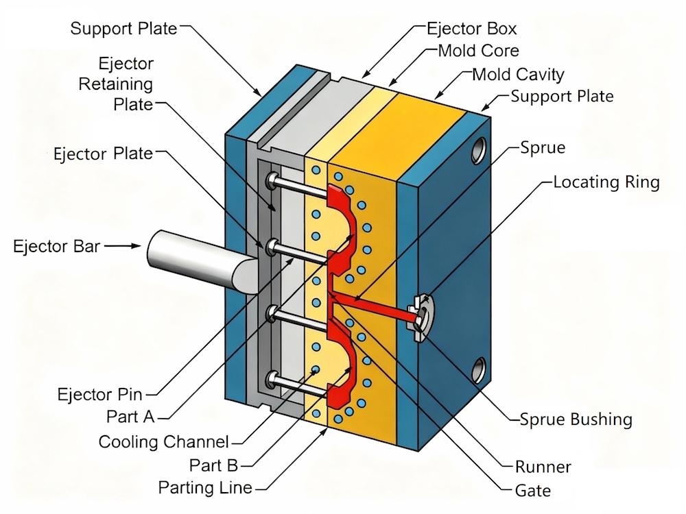
An Spritzguss Struktur bezieht sich auf das komplette mechanische System, das verwendet wird, um geschmolzenen Kunststoff in Endprodukte zu formen. Es besteht aus mehreren integrierten Systemen, die den Kunststofffluss, die Kühlung, die Ausrichtung, den Auswurf und die Bewegung während des Spritzgießzyklus steuern.
Im Gegensatz zu einem einfachen Werkzeug aus Metall ist ein Spritzgießwerkzeug eine Präzisionsbaugruppe, bei der jede Komponente mit hoher Genauigkeit zusammenwirken muss. Die Gesamtstruktur beeinflusst:
- Teilequalität
- Maßhaltigkeit
- Oberflächengüte
- Produktionsgeschwindigkeit
- Formbeständigkeit
- Wartungsanforderungen
- Herstellungskosten
Eine fachgerecht entworfene Werkzeugstruktur minimiert Produktionsfehler wie Gratbildung, Einfallstellen, Verzug, unvollständige Füllungen (Short Shots) und übermäßigen Verschleiß und maximiert gleichzeitig die Produktionseffizienz.
Hauptfunktionen einer Spritzgussform
| Funktion | Beschreibung |
|---|---|
| Umformtechnik | Formt geschmolzenen Kunststoff in die gewünschte Geometrie |
| Kühlung | Führt Wärme schnell und gleichmäßig ab, um die Zykluszeit zu verkürzen |
| Führung | Gewährleistet eine exakte Ausrichtung zwischen den Formenhälften |
| Auswurf | Gibtfertige Teilespäne beschädigungsfrei frei |
| Auslassen | Lässt eingeschlossene Luft beim Befüllen entweichen |
| Support | Behält die strukturelle Steifigkeit unter Einspritzdruck bei |
Grundkomponenten einer Spritzgussform
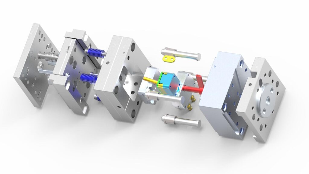
Obwohl sich die Strukturen von Formen je nach Produkt unterscheiden, beinhalten die meisten Spritzgießwerkzeuge mehrere grundlegende Systeme.
Standard-Formteile
| Komponente | Primärfunktion |
|---|---|
| Formaufbau | Unterstützt die vollständige Formmontage |
| Kern | Bildet die innere Geometrie des Kunststoffteils ab |
| Karies | Bildet die Außenfläche des Teils |
| Spritzbuchse | Überträgst geschmolzenen Kunststoff in das Angusssystem |
| Läufer | Verteilt geschmolzenen Kunststoff in der Form |
| Tor | Steuert den Materialeintritt in die Kavität |
| Kühlkanäle | Formtemperatur regeln |
| Auswurfsystem | Entfernt das Formteil |
| Führungssäulen & Buchsen | Sorgen Sie für eine präzise Ausrichtung |
| Rückholstifte | Setzen Sie das Auswerfersystem zurück. |
| Stützplatten | Formsteifigkeit erhöhen |
| Verschleißplatten | Reibung an beweglichen Bauteilen verringern |
Jedes Bauteil muss mit engen Toleranzen gefertigt werden, um eine stabile Produktion über Tausende – oder sogar Millionen – von Spritzgießzyklen zu gewährleisten.
Formaufbau: Das Fundament der Form
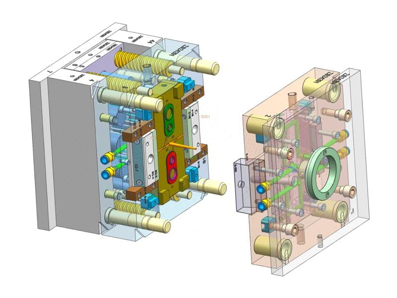
Der Formaufbau bietet strukturelle Unterstützung für alle anderen Formkomponenten. Er hält die Form während des Spritzgießens steif, sorgt für die Ausrichtung und nimmt bewegliche Systeme wie Auswerferplatten und Führungssäulen auf.
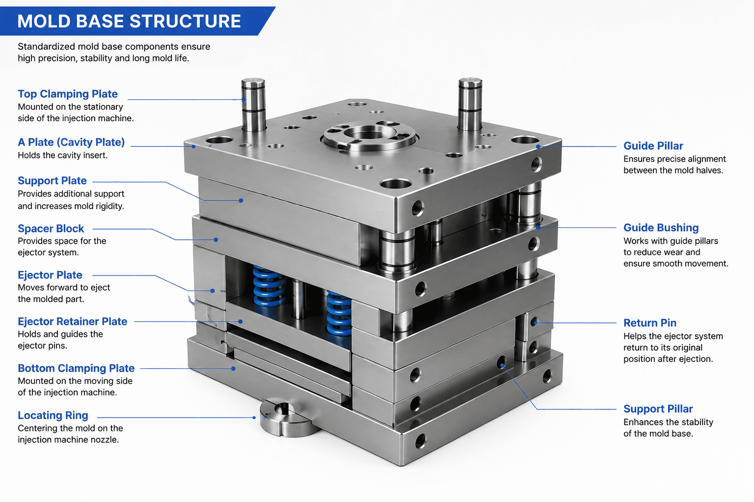
Die meisten professionellen Formenbauer verwenden standardisierte Formaufbausysteme von Herstellern wie HASCO, DME, LKM oder FUTABA. Die Standardisierung vereinfacht die Wartung, verkürzt die Durchlaufzeiten und gewährleistet die Kompatibilität mit Ersatzteilen.
Typische Normalien für den Formenbau
| Komponente | Zweck |
|---|---|
| Obere Spannplatte | Montiert die Form an die Spritzgießmaschine |
| Ein Teller | Hält den Formeinsatz |
| B-Platte | Hält den Kerneinsatz |
| Stützplatte | Verstärkt die Formstruktur |
| Abstandshalter | Platz für das Auswerfersystem schaffen |
| untere Spannplatte | Sichert die bewegliche Formhälfte |
Die Auswahl der Normaufnahmegröße hängt von den Bauteilabmessungen, der projizierten Fläche, dem Einspritzdruck und den Maschinenspezifikationen ab.
Kern und Formkavität: Erstellung der Produktform
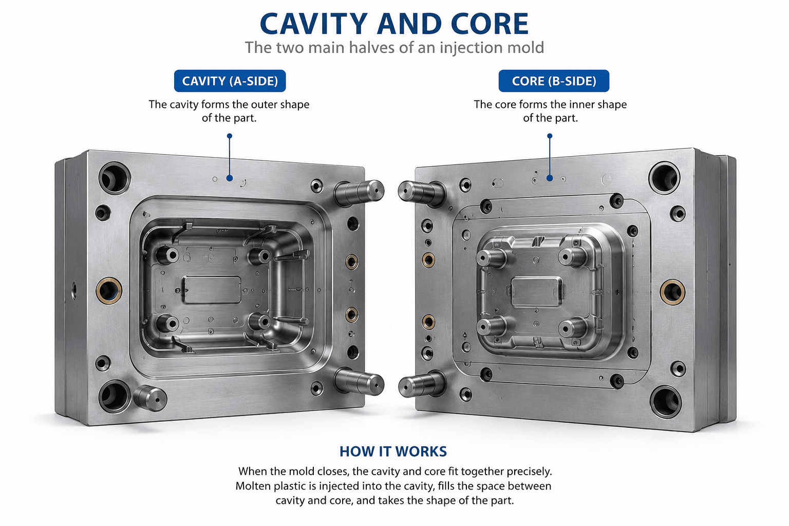
Die Kern und Karies sind das Herzstück jeder Spritzgießform. Zusammen definieren sie die endgültige Geometrie des Formteils.
- Der Hohlraum bildet die äußere Oberfläche des Produkts.
- Der Kern bildet die internen Merkmale wie Löcher, Rippen, Domen und Montagemrukturen.
Der Spalt zwischen Kern und Kavität bestimmt die Wandstärke des fertigen Kunststoffteils. Eine hohe Bearbeitungsgenauigkeit und eine ausgezeichnete Oberflächengüte sind unerlässlich, um Maßhaltigkeit und Produktoptik zu gewährleisten.
Gängige Formenbaustähle
| Stahlsorte | Eigenschaften | Typische Anwendungen |
|---|---|---|
| P20 | Gute Zerspanbarkeit, wirtschaftlich | Mehrzweckformen |
| 718H | Vorvergütet, hervorragende Polierbarkeit | Verbrauchsgüter |
| NAK80 | Hervorragende Spiegeloberfläche | Kosmetische und transparente Teile |
| S136 | Korrosionsbeständiger Edelstahl | Medizinische, optische und lebensmittelechte Formen |
| H13 | Hohe Hitzebeständigkeit | Hochtemperatur-technische Kunststoffe |
| 8407 | Lange Lebensdauer und Verschleißfestigkeit | Großserienfertigung |
Die Auswahl des richtigen Formenstahls hängt von der Harzart, dem jährlichen Produktionsvolumen, der erforderlichen Oberflächengüte und der erwarteten Lebensdauer der Form ab.
Läufersystem: Effiziente Förderung von geschmolzenem Kunststoff
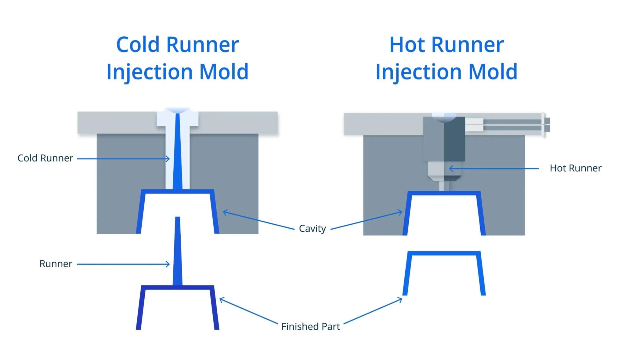
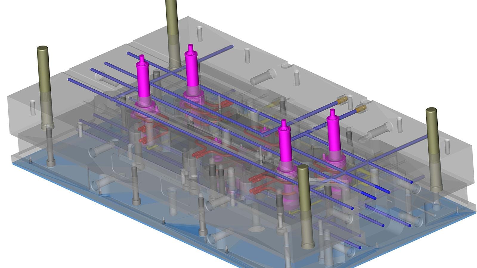
Das Angießsystem transportiert geschmolzenen Kunststoff von der Düse der Spritzgießmaschine in die Formkavität. Ein gut designtes Angießsystem sorgt für eine gleichmäßige Füllung, minimiert den Druckverlust und reduziert Materialabfall. Ein schlechtes Design des Angießsystems kann zu unvollständigen Spritzgussteilen, Bindenähten, übermäßigem Druck und inkonsistenter Bauteilqualität führen.
Es gibt zwei Haupt-Kansalsysteme, die in Spritzgießwerkzeugen verwendet werden:
| Lauftyp | Vorteile | Einschränkungen | Typische Anwendungen |
|---|---|---|---|
| Kaltkanal | Geringere Werkzeugkosten, einfache Wartung | Produziert Angussabfall | Allgemeine Verbrauchsgüter |
| Heißkanal | Kein Angussabfall, kürzere Zykluszeit | Höhere Werkzeuginvestitionen | Großserienfertigung, Sichtteile |
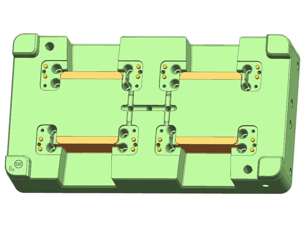
Für Mehrkavitäten-Werkzeuge sind ausgewogene Angusskanäle unerlässlich, um sicherzustellen, dass sich jede Kavität gleichzeitig füllt und Teile mit konsistenten Maßen und Aussehen entstehen.
Torsystem
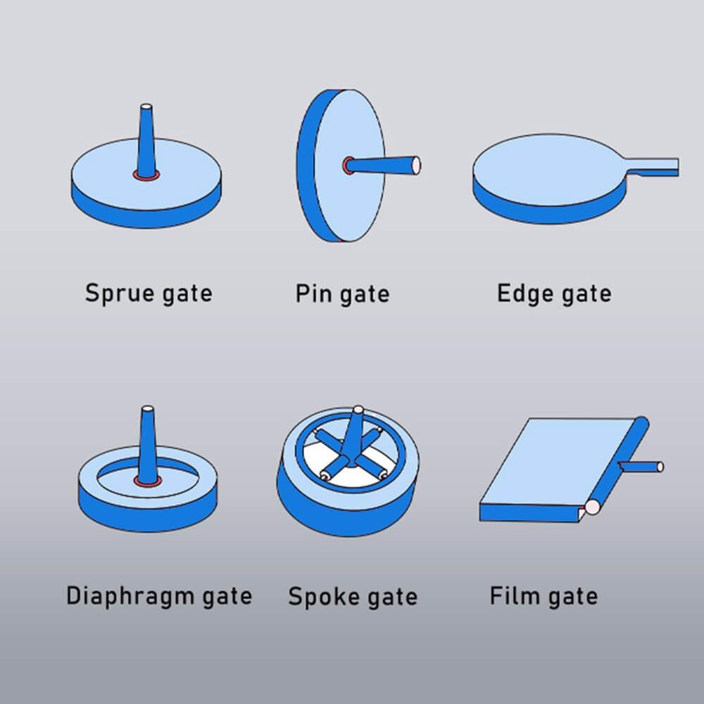
Der Anguss ist die letzte Öffnung, durch die geschmolzener Kunststoff in die Kavität gelangt. Seine Position, Größe und Art beeinflussen direkt das Füllverhalten, den Nachdruck, den Angussrückstand und die optische Qualität.
Gängige Gattertypen
| Torart | Am besten geeignet für | Vorteile |
|---|---|---|
| Edge Gate | Allgemeine Produkte | Einfache Bearbeitung und Wartung |
| Pin-Tor | Mehrkavitätenformen | Anschnitt |
| U-Boot-Tor | Automatisches Entangeln | Hohe Produktionseffizienz |
| Fan-Gate | Dünnwandige Bauteile | Gleichmäßiger Materialfluss |
| Vennentor | Hochwertige Anbauteile | Kein sichtbarer Anschnitt |
Bei der Anschnittauswahl sollten immer die Produktgeometrie, die Fließeigenschaften des Kunststoffs, die Wandstärke und die optischen Anforderungen berücksichtigt werden.
Kühlsystem
Die Kühlung macht etwa 50–70% der gesamten Spritzgießzykluszeit, womit es zu den wichtigsten Systemen innerhalb der Form gehört.
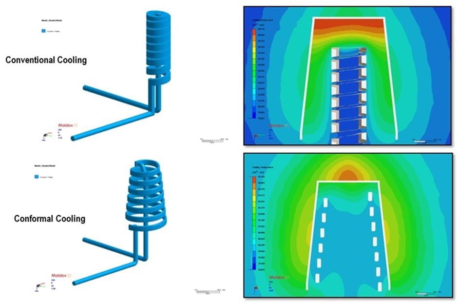
Ein richtig ausgelegtes Kühlsystem leitet Wärme gleichmäßig ab, verkürzt die Zykluszeit und minimiert gleichzeitig den Verzug und Maßabweichungen.
Gängige Kühlkomponenten
- Gerade Kühlkanäle
- Schallschutzlamellen
- Springbrunnen
- Spiralkühleinsätze
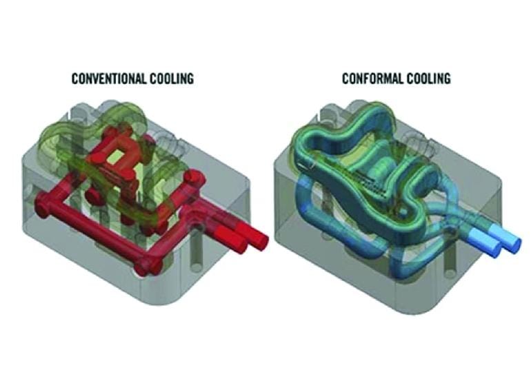
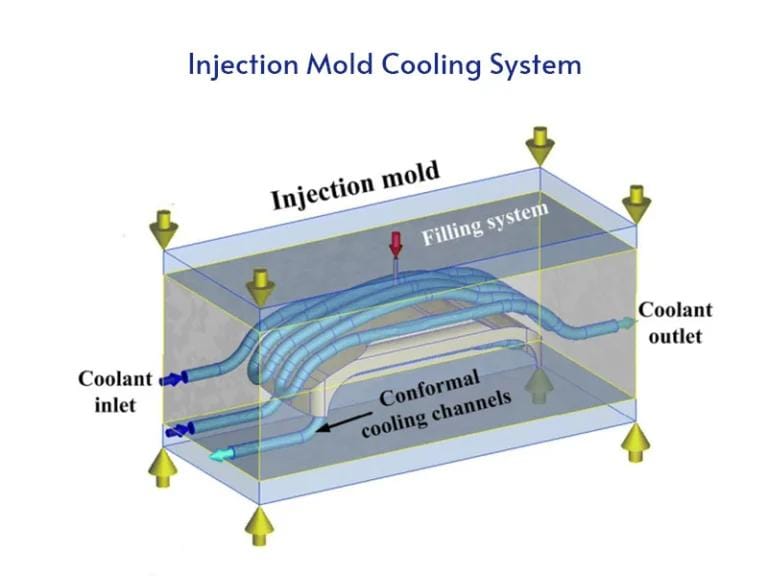
- Konformale Kühlung (3D-gedruckte Einsätze)
| Kühlmethode | Typische Anwendung | Vorteil |
|---|---|---|
| Gerade Kanäle | Standardformen | Günstig |
| Beflockungskühlung | Tiefenkerne | Verbesserte Wärmeableitung |
| Blasenkuhlung | Enge Kernbereiche | Bessere Temperaturregelung |
| Konturnahe Kühlung | Komplexe Formen | Maximale Kühleffizienz |
Auswurfsystem
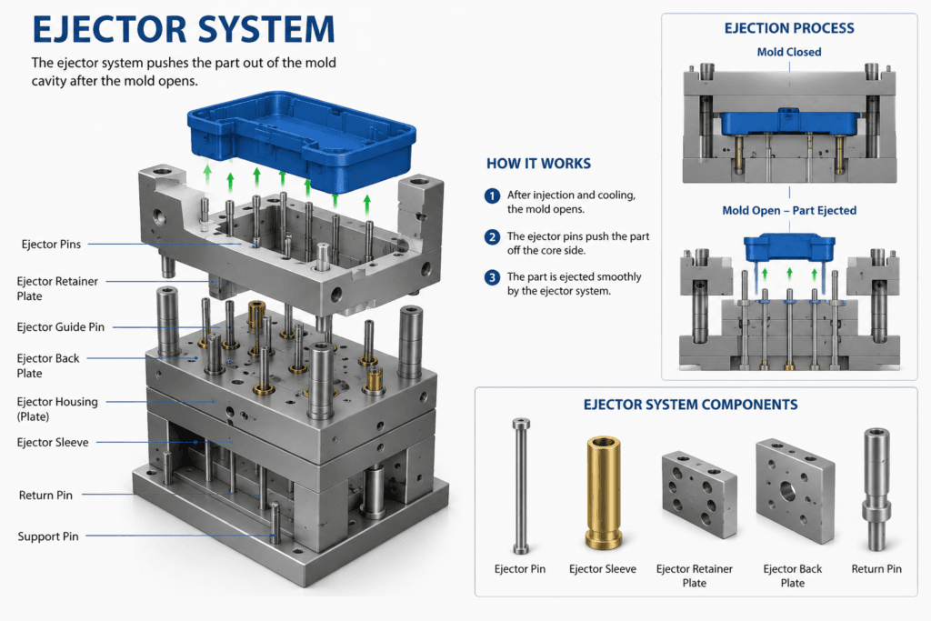
Nach dem Abkühlen muss das Formteil entnommen werden, ohne dessen Oberfläche oder Geometrie zu beschädigen. Das Auswerfersystem erfüllt diese Aufgabe, indem es eine kontrollierte Kraft auf das Formteil ausübt.
Gängige Auswurfmethoden
| Auswurfverfahren | Typische Produkte |
|---|---|
| Auswerferstifte | Die meisten Kunststoffteile |
| Hülsenauswerfer | Zylindrische Teile |
| Abstreiferplatte | Dünnwandige Behälter |
| Luftausstoß | Transparente Produkte |
| Hydraulische Auswerfung | Große Industrieteile |
Die richtige Platzierung der Auswerfer hilft, Verformungen, Weißbruch und Oberflächenmarkierungen zu verhindern.
Schieber- und Hebermechanismen
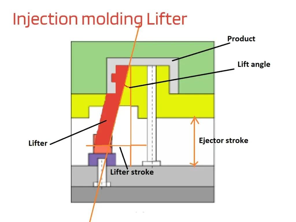
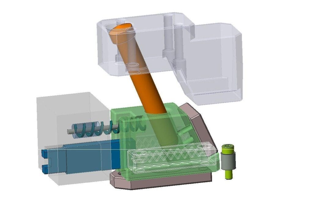
Viele Kunststoffteile weisen Unterschneidungen auf, die sich mit einer einfachen Zweigplattenform nicht entformen lassen. Zusätzliche Mechanismen wie Schieber und Schräghauben sind erforderlich.
Schieberegler
Schieber bewegen sich während des Öffnens der Form horizontal, um äußere Unterschneidungen zu entformen.
Typische Anwendungen umfassen:
- Seitenlöcher
- Karabinerhaken
- Kabelauslässe
- Anschlussfunktionen
Heber
Lifter bewegen sich gleichzeitig nach oben und nach außen, um innere Unterbleibungen zu entformen.
Typische Anwendungen umfassen:
- Interne Verriegelungslaschen
- Versteckte Clips
- Komplexe interne Geometrien
Diese Mechanismen erhöhen die Werkzeugkomplexität, ermöglichen aber hochfunktionale Bauteildesigns.
Entlüftungssystem
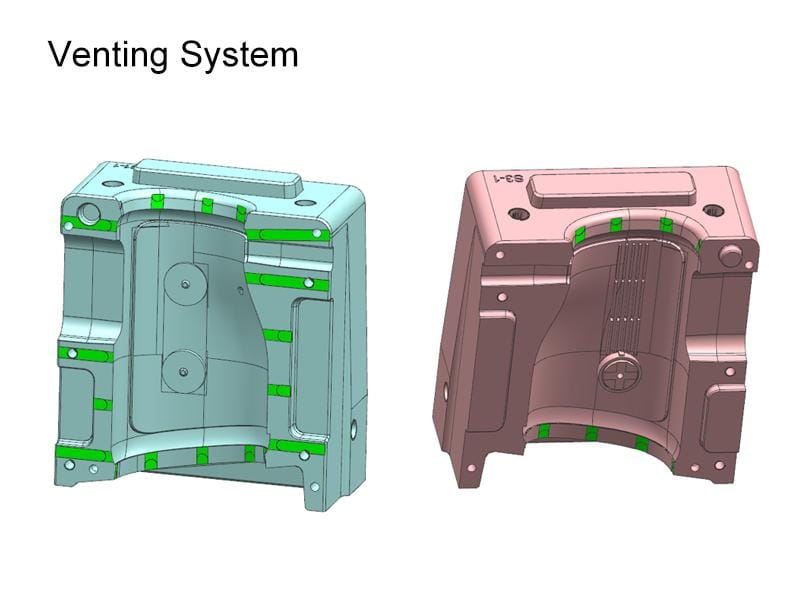
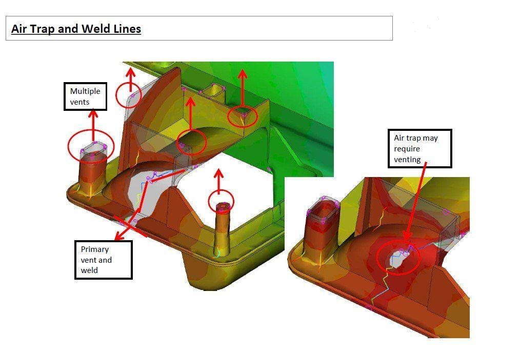
Beim Einspritzen muss eingeschlossene Luft aus der Kavität entweichen können. Ohne ausreichende Entlüftung können komprimierte Gase zu Fehlern führen wie:
- Brandspuren
- Kurze Schüsse
- Gasabscheider
- Mcige Oberflächengüte
- Unvollständige Füllung
Entlüftungsrillen werden typischerweise in die Trennebene oder an Auswerferstiftpositionen eingearbeitet und sorgfältig dimensioniert, um das Entweichen von Gas zu ermöglichen und gleichzeitig zu verhindern, dass geschmolzener Kunststoff als Grat austritt.
Herstellungsverfahren für Spritzgießwerkzeuge
Der Bau einer hochwertigen Form erfordert Präzisionstechnik und mehrere Bearbeitungsprozesse.
Typischer Fertigungsablauf
| Schritt | Beschreibung |
|---|---|
| Produktbewertung | Kundenzeichnungen und -anforderungen analysieren |
| DFM-Analyse | Produkt für die Herstellbarkeit optimieren |
| Moldflow-Simulation | Füllung, Kühlung und Verzug vorhersagen |
| Formenbau | Vollständige 3D-Formmontage entwickeln |
| CNC-Bearbeitung | Herstellung von Kern-, Kavitäten- und Formplatten |
| EDM & Drahterodieren | Komplexe Merkmale der Maschine |
| Polieren und Strukturieren | Erforderliche Oberflächengüte erreichen |
| Formmontage | Alle Formteile zusammenbauen |
| T1-Formversuch | Erste Muster erstellen |
| Prüfung und Optimierung | Maße und Leistung überprüfen |
| Endgültige Genehmigung | Form für die Serienfertigung vorbereiten |
Warum Samgo wählen?
Bei Samgo bieten wir umfassende Formenbaugießereilösungen vom Konzept bis zur Massenproduktion.
Unsere Kernleistungen
| Service | Kundennutzen |
|---|---|
| Produktdesign | Optimierte Herstellbarkeit |
| DFM-Analyse | Geringere Risiken bei der Werkzeugfertigung |
| Moldflow-Simulation | Verbesserte Formleistung |
| Präzisionsformenbau | Lange Lebensdauer der Form |
| Spritzgießen | Stabile Massenproduktion |
| Qualitätsprüfung | Gleichbleibende Produktqualität |
Unser Ingenieurteam konzentriert sich auf die Konstruktion von Formen, die die Produktivität maximieren, den Wartungsaufwand minimieren und über die gesamte Lebensdauer der Form hinweg eine zuverlässige Leistung gewährleisten.
Häufig gestellte Fragen (FAQ)
Was ist der wichtigste Bestandteil einer Spritzgussform?
Der Kern und die Kavität sind die wichtigsten Komponenten, da sie die endgültige Form, die Abmessungen und die Oberflächenqualität des Formteils bestimmen.
Was ist der Unterschied zwischen einem Heißkanal und einem Kaltkanal?
Ein Heißkanal hält den Kunststoff im Inneren der Form geschmolzen, wodurch Angussabfälle vermieden werden, während ein Kaltkanal nach jedem Zyklus erstarrt und entfernt oder recycelt werden muss.
Warum ist die Auslegung des Kühlsystems so wichtig?
Ein effizientes Kühlsystem verkürzt die Zykluszeit, verbessert die Maßhaltigkeit und verringert das Verziehen, wodurch es zu einem der wichtigsten Faktoren für die Produktionseffizienz wird.
Wann werden Gleitstücke und Hebevorrichtungen benötigt?
Sie werden verwendet, wenn Formteile Unterauchungen oder seitliche Elemente aufweisen, die sich nicht durch das Öffnen der Form in gerader Richtung entformen lassen.