
Оглавление
Введение
Draft angle is a fundamental consideration in литьевая форма design, but its importance extends far beyond allowing a plastic component to leave the mold. A properly designed draft angle influences surface quality, ejection force, dimensional accuracy, mold maintenance and overall production efficiency.
Insufficient draft can cause scratches, deformation, difficult ejection and premature wear of mold components. Excessive draft, however, may affect product appearance, assembly clearances and functional dimensions.
For mold designers, the objective is not simply to apply the largest possible draft angle. It is to determine an appropriate angle for each surface according to its geometry, material, texture and functional requirements.
1. How Draft Angle Affects Part Ejection
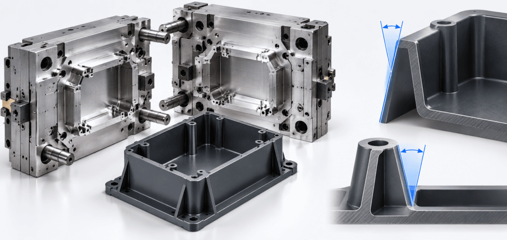
Draft angle is the slight taper applied to a molded surface in the direction of mold opening. It allows the component to separate progressively from the cavity or core instead of maintaining full contact throughout ejection.
During cooling, plastic often contracts around the mold core. This contraction creates contact pressure and friction between the plastic and steel surfaces.
When a vertical wall has insufficient draft, ejector pins must overcome greater resistance. Excessive ejection force can cause stress whitening, distortion, ejector marks or damage to thin structural features.
Introducing draft reduces contact as the part moves away from the mold surface. This can improve ejection consistency and reduce the risk of production interruptions.
Internal surfaces deserve particular attention because plastic shrinkage can increase the gripping force around the core.
2. Recommended Draft Angles for Different Surfaces
There is no universal draft angle suitable for every injection molded component.
The required angle depends on wall depth, material characteristics, surface finish, mold construction and the position of the parting line.
The following values are preliminary design guidelines rather than fixed manufacturing requirements.
Surface or feature | Preliminary draft angle | Design consideration |
|---|---|---|
Smooth external walls | 0.5°–1° | Shallow, polished surfaces |
General housing walls | 1°–2° | Common starting range |
Internal walls | 1°–2° | Consider shrinkage around cores |
Lightly textured surfaces | 1.5°–3° | Depends on texture depth |
Deep textured surfaces | 3°–5° or more | Confirm with texture supplier |
Deep ribs and pockets | 0.5°–2° | Depends on depth and geometry |
A polished surface may release successfully with relatively little draft, while a heavily textured surface generally requires more.
These values should be verified against the selected resin, surface specification and actual tooling conditions.
3. Draft Angle and Surface Texture
Surface texture is one of the most frequently underestimated factors in draft-angle design.
Textured surfaces contain microscopic peaks and valleys. If a component is pulled vertically against these features, the surface can experience excessive friction.
Insufficient draft may produce dragging marks, uneven texture or localized surface damage.
The deeper the texture, the more clearance is generally required during ejection.
For example, a smooth consumer-electronics housing and a heavily textured outdoor equipment enclosure may require different draft angles even when their wall thickness and overall dimensions are identical.
Texture specifications should therefore be confirmed before the mold cavity is finished. Adding a deep texture late in development can create difficulties if the existing geometry has insufficient draft.
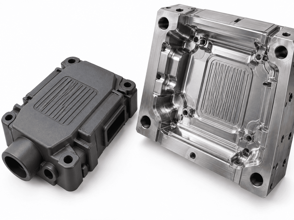
4. How Draft Angle Influences Product Dimensions
Draft angle changes the dimensions of a component along the height of its walls.
Consider a plastic enclosure with a wall height of 40 mm and a draft angle of 1.5°. The dimensional difference between the top and bottom of each drafted wall is approximately 1.05 mm.
For two opposing walls drafted symmetrically, the overall width difference may reach approximately 2.10 mm.
This difference can be significant when designing components that must fit into an existing assembly.
Engineers should clearly define whether critical dimensions apply at the parting line, the bottom of a housing or another specified reference plane.
A common mistake is adding draft after the functional dimensions have already been finalized. This can unintentionally change mating surfaces, mounting positions or assembly clearances.
Draft requirements should therefore be incorporated during the initial CAD design rather than treated as a final tooling adjustment.
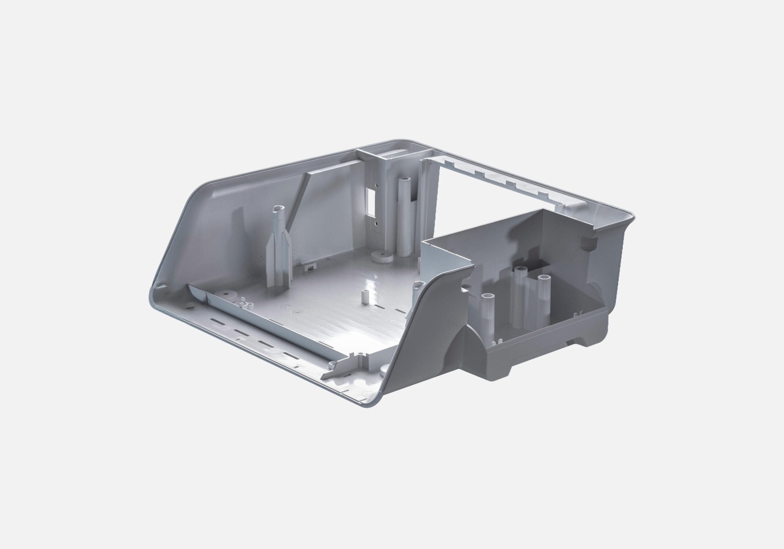
5. Draft Design for Ribs, Bosses and Deep Cavities
Structural features often present greater drafting challenges than simple external walls.
Deep ribs have long contact surfaces and limited space for tapering. Excessive draft can make their tips too thin, while insufficient draft can increase ejection resistance.
Screw bosses present a similar challenge. Their internal holes require suitable draft, but the remaining wall thickness must still support the intended fastening method.
Deep cavities may also create vacuum resistance during ejection. In these situations, draft alone may not solve the problem; appropriate venting and ejection arrangements may also be necessary.
Функция | Main drafting challenge | Design approach |
|---|---|---|
Deep ribs | Thin rib tips | Balance depth, thickness and taper |
Screw bosses | Reduced wall thickness | Check boss strength and hole dimensions |
Tall housing walls | Large dimensional difference | Define critical reference dimensions |
Deep internal pockets | High ejection resistance | Combine draft with suitable ejection |
Snap-fit features | Functional geometry | Evaluate local draft and possible undercuts |
6. What Happens When a Product Cannot Accommodate Draft?
Some components require nearly vertical walls because of assembly, sealing or aesthetic requirements.
A designer should first determine whether the zero-draft requirement is genuinely functional or simply a consequence of the original CAD geometry.
In certain cases, the parting line can be repositioned or the mold opening direction modified to accommodate the required geometry.
For localized features, slides, lifters or removable inserts may provide alternative tooling solutions.
However, these mechanisms introduce additional manufacturing costs, maintenance requirements and potential dimensional variation.
A zero-draft surface should therefore be a deliberate engineering decision supported by the mold manufacturer rather than an overlooked design condition.
7. Draft Analysis Before Mold Manufacturing
Draft analysis is an important CAD-based verification step before tooling begins.
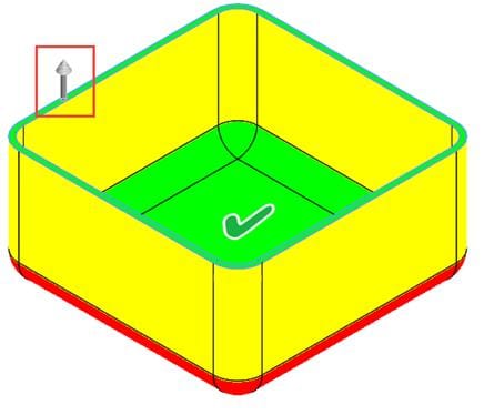
Software such as Siemens NX can evaluate surface angles relative to the proposed mold-opening direction. Color-coded analysis helps engineers identify positive draft, negative draft and near-zero-draft surfaces.
Particular attention should be given to deep internal walls, textured surfaces, snap-fit features and areas that may require side actions.
The results should be reviewed together with the proposed parting line, core and cavity arrangement, ejection system and critical dimensional requirements.
Early analysis helps identify surfaces that would otherwise require expensive steel modifications after the first mold trial.
8. Draft Angle and Long-Term Mold Performance
Proper draft design can also reduce tooling maintenance.
Repeated high-friction ejection may gradually damage polished or textured mold surfaces. This is particularly relevant to deep cavities and components produced in large quantities.
Adequate draft helps reduce unnecessary surface contact and can improve consistency over long production runs.
Nevertheless, draft must be considered together with mold steel selection, surface treatment, cooling efficiency and ejection design.
A well-designed mold achieves reliable part release without compromising the appearance or functionality of the finished component.
Заключение
Draft angle is a small geometric feature with a substantial influence on injection molding performance.
Its value lies in balancing part ejection, surface texture, dimensional requirements and mold complexity. Applying an arbitrary angle to every surface is rarely appropriate for precision components.
By evaluating draft early, defining critical dimensions and reviewing challenging features before tooling, manufacturers can reduce mold modifications, protect finished surfaces and improve production consistency.
Узнать актуальную цену? Мы ответим как можно скорее (в течение 12 часов)
Draft Angle in Injection Mold Design: Improving Part Quality, Ejection and Tooling Efficiency
Discover how draft angles affect injection mold design, part ejection, surface texture, dimensional accuracy, ribs, bosses and long-term tooling performance.
Injection Molding Shrinkage: How to Control Part Dimensions from Mold Design to Production
Learn how injection molding shrinkage affects mold dimensions, tolerances and warpage, and how material, gate design, packing, cooling and mold trials help control final plastic part dimensions.
How to Choose the Right Injection Molding Supplier: A Practical Buyer’s Guide
Learn how to choose a reliable injection molding supplier by evaluating DFM capability, mold manufacturing, materials, quality control, production capacity, pricing, mold maintenance and technical communication.